
|
Size: 1433
Comment:
|
← Revision 59 as of 2012-01-03 23:02:40 ⇥
Size: 3379
Comment: converted to 1.6 markup
|
| Deletions are marked like this. | Additions are marked like this. |
| Line 1: | Line 1: |
| <<TableOfContents(3)>> | |
| Line 2: | Line 3: |
| [[Past_Plans]] | |
| Line 5: | Line 7: |
| * '''Pre-vent works''' * Tuning of the MC servo ~ low power MC test * End transmon X/Y Optics relocations (before the vent) for green * ITM pointing preparations? (green/red pointers at the both ends) |
|
| Line 10: | Line 8: |
| * '''Vent''' * What to do before the vent? * Tuning of the MC servo ~ low power MC test * ITM pointing preparations? (green/red pointers at the both ends) |
* '''IOO work''' * '''[DONE]''' Moving faraday and input optics |
| Line 15: | Line 11: |
| * '''ITM placement''' * What to do before the ITM placement? * Suspension assembly * Gluing test * Optics cleaning * Gluing (magnets/standoffs/guide rods) * Suspending * procedure |
* '''MMT placement / initial pointing adjustment''' * '''[DONE]''' MC trans beam mode measurement * '''[DONE]''' Renew the MMT solution |
| Line 24: | Line 15: |
| * '''MMT placement''' * What to do before the MMT placement? * Optics delivery (Shipping Feb 25) / baking |
* '''[DONE]''' MMT placement * '''[DONE]''' Corridor projection ~ measuremnt & adjustment * '''[DONE]''' Initial Pointing adjustment |
| Line 28: | Line 19: |
| * '''Initial Pointing adjustment''' | * '''[DONE]''' ITMX/Y oplev |
| Line 31: | Line 22: |
| * What to do before the SRM/PRM/BS placement? * TT |
* '''[DONE]''' What to do before the SRM/PRM/BS placement? * '''[DONE]''' TT ==> TT preparations |
| Line 34: | Line 25: |
| * Closing up the vacuum | * '''[DONE]''' AUX optics alignment * '''[DONE]''' Closing up the vacuum |
| Line 37: | Line 30: |
| == Suspension preparation == | |
| Line 38: | Line 32: |
| == Green team == * ''' before vent''' * relocation of existing optics at the end table * '''during vent''' * set up the green stuff onto the end table * align the green laser to the cavity (how to ?) * mode matching of the green laser to the cavity * ''' after closing the tanks''' * recover IP-ANG and optical levers --------- == CDS team == * |
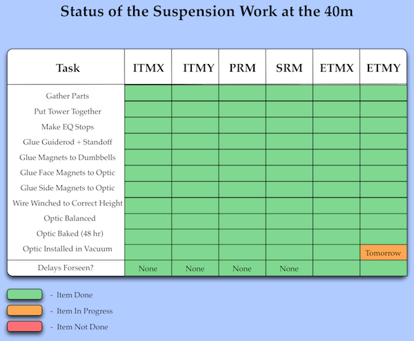
{{attachment:StatusTable.png}} |
| Line 55: | Line 35: |
| == Green team == * ''' before vent''' * relocation of existing optics at the end table -''take 1.5day'' * '''during vent''' * PLL measurement (9 Mar - 9? Apr) * set up the green stuff onto the end table * align the green laser to the cavity * how to: visual alignment * mode matching of the green laser to the cavity * on the table / corridor projection test ==> sliding mount * ''' after tank evacuation''' * recover IP-ANG and optical levers |
|
| Line 56: | Line 48: |
| --------- == CDS team == * 2/22-3/5 Delivery of some computers? / CDS software installations? * -3/31 Installation for some of the suspensions? --------- |
|
| Line 58: | Line 56: |
| --------- | * Conversion of the RF Photodetectors as in the table [[Upgrade 09/RF System|here]] * Removal of the photodetectors from the optics tables: REFL33 (PD2), REFL199 (PD6), REFL166 (PD11), AS166 (PD1), AS133 (PD9), POX33 (PD3), POY33 (PD4), PO133 (PD7-8), PO199 (PD7-8) * Replacement of the diodes: 2mm PDs for REFL11 (AM Monitor PD), REFL33 (PD2), REFL55 (PD6), AS55 (PD9) , POX11 (PD3) , POY11 (PD4); 1mm for REFL166(PD11), AS166(PD1), POP22-POP110(PD7-8) * Adjustment for PDs' boards for the change of capacitance due to the new diodes * Tune the resonant frequencies of the the old SPOB66, PD6, PD9, PD3, PD4, PD7-8 |
| Line 60: | Line 62: |
| == PSL table upgrade == | |
| Line 62: | Line 63: |
| * Laser delivery (done) * |
* Modification of the demod board * Installation of the low/high/band pass filters * Prepare for building the [[Upgrade_09/RF_System/RF_Modulation_Generator|RF Modulation Generator Box]] and of [[Upgrade_09/RF_System/RF_Distribution_Box|RF Distribution Box]] * RG-174 cables for the internal wiring * prepare the powering system * get RG-174 cables for the internal wiring * get 2 aluminum slabs from the machine shop * Commissioning of AS55 PD * Improvement of the REFL55 PD response * Improvement of REFL11 PD by introducing and additional notch at 55MHz * Commissioning of POX and POY PDs * Design and commissioning of SPOB * Design and commissioning of 3f PDs: * REFL33 * REFL165 * AS165 * Construction of the frequency generation box * Continuing construction of frequency generation box * Commissioning of the frequency generation * construction and commissioning of the frequency ''distribution'' box for the LSC rack * modification of the demod boards * commissioning of the frequency distribution system * LSC rack cabling and setup * Clearing of the old cabling * Cabling to the EOM * Cabling to the LSC Rack * Installation of the new modulation and demodulation chassis * EOM installation |
Contents
40m upgrade installation plan
Main optics team
IOO work
[DONE] Moving faraday and input optics
MMT placement / initial pointing adjustment
[DONE] MC trans beam mode measurement
[DONE] Renew the MMT solution
[DONE] MMT placement
[DONE] Corridor projection ~ measuremnt & adjustment
[DONE] Initial Pointing adjustment
[DONE] ITMX/Y oplev
SRM/PRM/BS placement
[DONE] What to do before the SRM/PRM/BS placement?
[DONE] TT ==> TT preparations
[DONE] AUX optics alignment
[DONE] Closing up the vacuum
Suspension preparation
Green team
before vent
relocation of existing optics at the end table -take 1.5day
during vent
- PLL measurement (9 Mar - 9? Apr)
- set up the green stuff onto the end table
- align the green laser to the cavity
- how to: visual alignment
- mode matching of the green laser to the cavity
on the table / corridor projection test ==> sliding mount
after tank evacuation
- recover IP-ANG and optical levers
CDS team
- 2/22-3/5 Delivery of some computers? / CDS software installations?
- -3/31 Installation for some of the suspensions?
RF team
Conversion of the RF Photodetectors as in the table here
- Removal of the photodetectors from the optics tables: REFL33 (PD2), REFL199 (PD6), REFL166 (PD11), AS166 (PD1), AS133 (PD9), POX33 (PD3), POY33 (PD4), PO133 (PD7-8), PO199 (PD7-8)
- Replacement of the diodes: 2mm PDs for REFL11 (AM Monitor PD), REFL33 (PD2), REFL55 (PD6), AS55 (PD9) , POX11 (PD3) , POY11 (PD4); 1mm for REFL166(PD11), AS166(PD1), POP22-POP110(PD7-8)
- Adjustment for PDs' boards for the change of capacitance due to the new diodes
- Tune the resonant frequencies of the the old SPOB66, PD6, PD9, PD3, PD4, PD7-8
- Modification of the demod board
- Installation of the low/high/band pass filters
Prepare for building the RF Modulation Generator Box and of RF Distribution Box
- RG-174 cables for the internal wiring
- prepare the powering system
- get RG-174 cables for the internal wiring
- get 2 aluminum slabs from the machine shop
- Commissioning of AS55 PD
- Improvement of the REFL55 PD response
- Improvement of REFL11 PD by introducing and additional notch at 55MHz
- Commissioning of POX and POY PDs
- Design and commissioning of SPOB
- Design and commissioning of 3f PDs:
- REFL33
- REFL165
- AS165
- Construction of the frequency generation box
- Continuing construction of frequency generation box
- Commissioning of the frequency generation
construction and commissioning of the frequency distribution box for the LSC rack
- modification of the demod boards
- commissioning of the frequency distribution system
- LSC rack cabling and setup
- Clearing of the old cabling
- Cabling to the EOM
- Cabling to the LSC Rack
- Installation of the new modulation and demodulation chassis
- EOM installation