
Slow Controls
Old Slow Controls Machines (Pre-2017)
Contents
Auxiliary DAQ Modules
The auxiliary DAQ system uses the Acromag XT series DIN-rail mounted ADC, DAC and BIO modules. The model numbers are in the format XTYYY1, where "XT" is a static prefix, "YYY" determines the function, and the "1" as the last digit denotes the ModBus/TCP version of the model. The 1 at the end is important, as the other variations will not be able to interface with CDS through EPICS.
Module |
Function |
# Channels |
Notes |
Manual |
XT1111 |
BIO |
16 |
Sinking outputs |
|
XT1121 |
BIO |
16 |
Sourcing outputs |
|
XT1221 |
ADC |
8 |
Differential inputs |
|
XT1541 |
DAC |
8 |
4 sourcing output BIO channels |
HowTo
Configure auxiliary DAQ host machine
The following has proven to work with Debian Jessie (x64) on a Supermicro SYS-5017A-EP.
- Fresh install of Debian Jessie (or most recent stable release)
Username: controls
Optional: lightweight desktop environment LXDE
Give sudo privileges to user controls
su
usermod -aG sudo controls
- Set up SSH access
- Run
sudo apt-get install openssh-client
Add lines "search martian" and "nameserver 192.168.113.104" to /etc/resolv.conf
- Run
- Set up martian and local ethernet adapters
- Edit /etc/network/interfaces as follows:
allow-hotplug eth0 iface eth0 inet static address 192.168.113.XX netmask 255.255.255.0 gateway 192.168.113.2 dns-nameservers 192.168.113.104 131.215.125.1 131.215.139.100 dns-search martian allow-hotplug eth1 iface eth1 inet static address 192.168.11Y.1 netmask 255.255.255.0 network 192.168.11Y.0 broadcast 192.168.11Y.255 - XX is a placeholder for the machine's IP on the martian network
- Y is placeholder for the IP root of the local subnet
Hostname
Martian IP
Local IP
C1SUSAUX
192.168.113.???
192.168.115.1
C1AUXEX
192.168.113.???
192.168.114.1
C1AUXEY
192.168.113.???
192.168.11?.1
C1PSL
192.168.113.???
192.168.11?.1
C1VAC
192.168.113.???
192.168.11?.1
C1???
192.168.113.???
192.168.11?.1
- Edit /etc/network/interfaces as follows:
- Set up remote file system access
- Run
sudo apt-get install nfs-common
mkdir /cvs/cds
Add line "chiara:/home/cds /cvs/cds nfs rw,bg,nfsvers=3" to end of /etc/fstab and run
- Run
- Install procserv for proper detaching of Modbus IOC systemd service
sudo apt-get install procserv
Configure Acromag XT modules
Initial configuration via USB is required before the units can be used on the network. This requires:
- USB-to-miniUSB cable
- Microsoft Windows (virtual) machine
Configuration Utilities: 9500465D.zip
The above zip file contains the setup executable to install the configuration software for all different modules. Depending on the module, a different version of the utility needs to be launched after install. As during operation, the to-be-configured device needs to be powered by a 12-32V DC voltage source, either through the designated blue plug-in terminal on the bottom, or the clip-on dock on the rail.
On a virtual machine it may be necessary to open some ports to allow the guest OS to access the physical USB device.
In USB Settings:
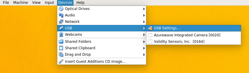
add a corresponding filter:
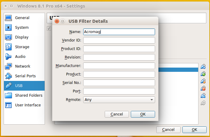
The vendor ID and product ID can be found via lsusb
Network Configuration
The primary screen of the configuration utilities looks identical for all models:
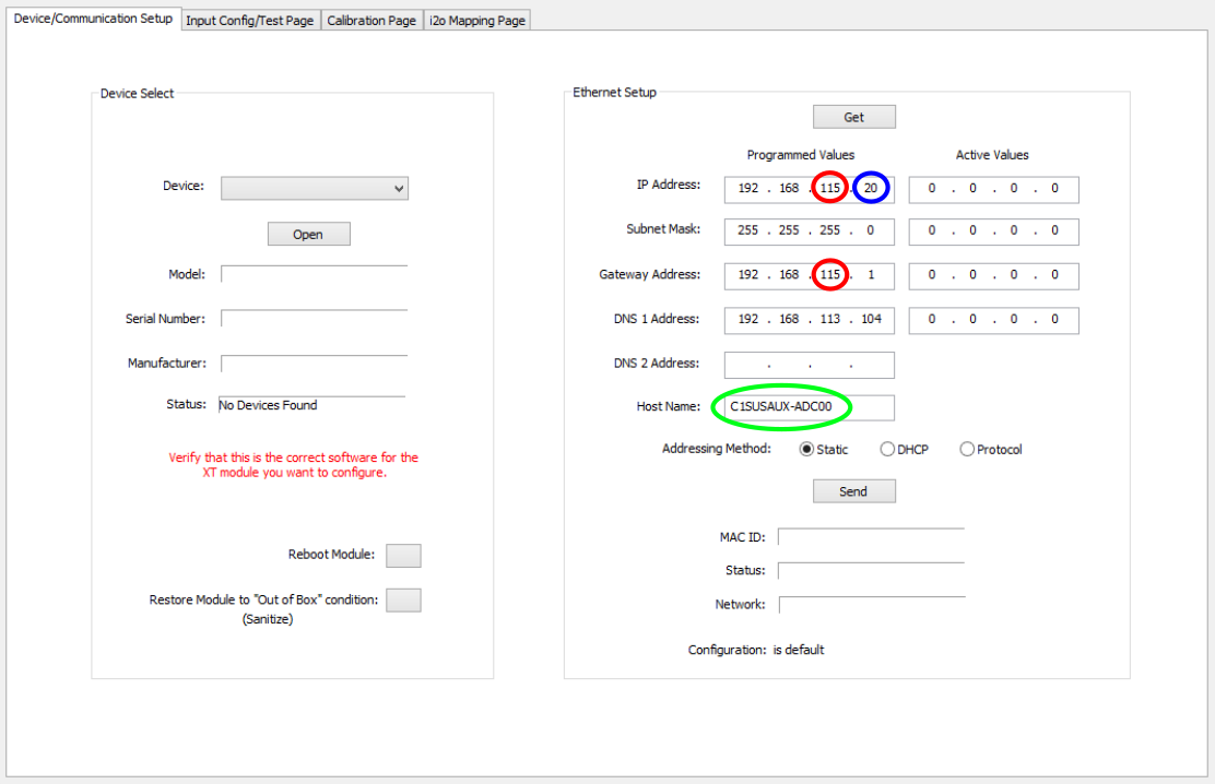
Once the device is connected to the host via USB and the correct application has been launched, it will appear in the drop down menu. On the right the device IP and other network parameters can be set. Every host machine of the auxiliary DAQ acts as a node between the martian network and a local subnet to which the Acromag modules belong and which is not directly accessible from other machines on the martian network.
- For consistency, the ADC, DAC, and BIO modules occupy different IP address spaces:
Module
Local IP Address Space
ADC
20-39
DAC
40-59
BIO
60-79
- Hostname and IP on the local network are assigned according to the following scheme:
Hostname
Local IP
C1XXX-ADCYY
192.168.11X.YY+20
C1XXX-DACYY
192.168.11X.YY+40
C1XXX-BIOYY
192.168.11X.YY+60
- Other settings (of no practical significance) are
- Gateway is the local IP of the node machine
- DNS is that of Chiara on the martian network: 192.168.113.104
Configure XT unit Modbus driver
# Use the following commands for TCP/IP
# drvAsynIPPortConfigure(const char *portName,  # user-defined: used for subsequent referencing,
#                        const char *hostInfo,  # format: "IP-Address:Port". Standard port for Modbus is 502
#                        unsigned int priority, #
#                        int noAutoConnect,     #
#                        int noProcessEos);     #
#
# Examples:
# drvAsynIPPortConfigure("<TCP_PORT_NAME>","<UNIT_IP_ADDRESS>:502",0,0,1)
# drvAsynIPPortConfigure("c1auxex_xt1221a","192.168.114.11:502",0,0,1)
# modbusInterposeConfig(const char *portName, # reference to portName created with drvAsynIPPortConfigure command
# modbusLinkType linkType, #
# int timeoutMsec, # define timeout for waiting for response from unit
# int writeDelayMsec) #
#
# Example:
# modbusInterposeConfig("<TCP_PORT_NAME>",0,5000,0)
# modbusInterposeConfig("c1auxex_xt1221a",0,5000,0)#drvModbusAsynConfigure(portName, # used by channel definitions in .db file to reference this unit)
# tcpPortName, # reference to portName created with drvAsynIPPortConfigure command
# slaveAddress, #
# modbusFunction, # defines driver function for the unit (read register = 4, write register = 6, write single coil = 5) - see examples in next section
# modbusStartAddress, # ADC and binary channel numbering starts with 0, DAC channel numbering with 1
# modbusLength, # length in dataType units - see examples in next section
# dataType, # 4 = 16-bit signed integers (for A/D and D/A), 0 = binary (for BIO, duh)
# pollMsec, # how frequently to request a value in [ms]
# plcType); #
#
# Example:
# drvModbusAsynConfigure("<PORT_NAME>","<TCP_PORT_NAME>",0,<modbusFunction>,<modbusStartAddress>,<modbusLength>,<dataType>,<pollMsec>,"Acromag")
XT1221
drvModbusAsynConfigure("C1AUXEX_XT1221A_ADC","c1auxex_xt1221a",0,4,0,8,4,32,"Acromag")
XT1541
drvModbusAsynConfigure("C1AUXEX_XT1541A_DAC","c1auxex_xt1541a",0,6,1,8,4,32,"Acromag")
drvModbusAsynConfigure("C1AUXEX_XT1541A_BIO","c1auxex_xt1541a",0,5,0,4,0,32,"Acromag")
XT1111 & 1121
drvModbusAsynConfigure("C1AUXEX_XT1111A_BIO","c1auxex_xt1111a",0,6,0,4,0,32,"Acromag")
Define EPICS channels
Note: Modbus/TCP is simply a protocol for sending commands via TCP that the XT units can interpret, as in read/write the correct register values to/from the channels. There may be multiple ways to define the channels have the same effect. The settings reported here have been found to work as intended.
Many of the fields in the EPICS records are somewhat supplemental and not required for the channel definitions, but some have real effect in MEDM screens, such as upper limits on slider bars and the such.
XT1221
field(INP,"@asynMask(<ADC_UNIT_PORT_NAME> 0 -16)MODBUS_DATA")
XT1541
record(ao, "<AO_CHANNEL_NAME>")
{
        field(DTYP,"asynInt32")
        field(OUT,"@asynMask(<DAC_UNIT_PORT_NAME>, 0, -16)MODBUS_DATA")
}
record(bo, "<BO_CHANNEL_NAME>")
{
field(DTYP,"asynUInt32Digital")
field(OUT,"@asynMask(<DAC_UNIT_PORT_NAME>, 3, 0x1)")
}
XT1111 & 1121
record( bo, "CHANNEL_NAME")
{
        field(DTYP,"asynUInt32Digital")
        field(OUT,"@asynMask(BIO0_Reg, 0, 0x1)")
}