
|
Size: 1897
Comment:
|
Size: 6300
Comment:
|
| Deletions are marked like this. | Additions are marked like this. |
| Line 1: | Line 1: |
| ## page was renamed from Upgrade 09/CDS/September CDS plan | |
| Line 2: | Line 3: |
== Major Missions == . {*} Complete damping of the vertex suspensions . {*} Preparation for Green locking . {*} Simulated plants [[BR]] == Useful Links == || ''''' category'''''|| ''''' description ''''' || ''''' Links '''''|| ||<|3> plans and overviews|| ''' CDS home page ''' || [:Upgrade_09/CDS] || || ''' CDS plan for August ''' || [:Upgrade_09/CDS/August_CDS_test] || || ''' Simulated Plant''' ||[:Simulated_Plant] || ||<|2> Lists || ''' Current Hardware Lists ''' || [:Upgrade_09/CDS/current_hardware] || || ''' Channel Assignments for C1SUS ''' || [:Upgrade_09/CDS/Suspension_wiring_to_channels] || ||<|3> Technical Notes || ''' Notes about CDS realtime code ''' || [:Notes_on_getting_the_CDS_Realtime_Code_Generator_working] || || ''' Notes for Green Locking interface to realtime code ''' || [:Notes_for_Green_locking_interface_to_RCG] || || ''' Notes for Simulated Plant ''' ||[:Notes_for_the_RCG_40m_simulated_plant] || [[BR]] ---------------- = PLANS = == TO DO LIST == || attachment:green.png '''complete'''|| attachment:orange.png '''intermediate state ''' || attachment:red.png '''incomplete''' || attachment:black.png gave up|| [[BR]] . ''' A. Complete suspension damping keeping in mind Version B coils. (1-2 days?) ''' . ''' ADC break out boards ''' . attachment:orange.png design an adapter box for the breakout boards . attachment:red.png make the box and install it . ''' Binary Output working on c1sus (Alex/Joe) 1-2 days ''' . attachment:orange.png rearrange the channel assignments . attachment:orange.png test all the BO channels and their assignments . attachment:green.png Switching over cabling from the current XY220's to the new system . ''' damping test with the BOs''' . attachment:green.png damping all the vertex suspensions with the new CDS . attachment:green.png check if the binary outputs are working . attachment:orange.png make the daq daemon work . ''' refinement of the control model ''' . attachment:green.png renewal of realtime control model . attachment:orange.png renewal of medm screens for the vertex suspensions . attachment:orange.png separate optics into some realtime models instead of one model in order to avoid run time issues . ''' misc. ''' . attachment:green.png fix {{{ feCodeGen.pl }}} script [[BR]] . ''' B. Preparation for Green Locking ''' . ''' Get RFM working (3-4 days) ''' . attachment:green.png make a new IPC parser . attachment:green.png string the RFM optical fiber connecting C1SUS and C1ISCEX . attachment:green.png switching the RFM old network to that of the new one by using the RFM bypath . attachment:green.png install PCI-5565 driver if it's necessary . attachment:orange.png test the RFM card by running the diagnostic script . attachment:orange.png test the RFM with the epics . ''' Get both end stations working ''' . attachment:red.png Check we have correct number of cables . attachment:green.png Check if both end stations are correctly running . ''' Get IOO front end machine working ''' . attachment:green.png Move the computer into 1X2 rack . attachment:green.png remove Marconi(?) and put a new IO chassis on 1X2 rack . attachment:green.png check timing/ADC/DAC on the IO chassis. And make it works (5 days) . ''' Fix non-working IO chassis ''' . attachment:green.png Check on fiber with Rolf for LSC . attachment:green.png timing/ADC/DAC check [[BR]] . ''' C. Simulated Plant ''' . ''' Simulated Green Locking ''' . attachment:green.png conceptual design . attachment:green.png make realtime simlink model . attachment:orange.png compile and install the model . ''' LSC simulated plant ''' . attachment:green.png conceptual design . attachment:green.png make realtime simlink model . attachment:orange.png compile and install the model . ''' SUS simulated plant ''' . attachment:red.png renew the model with the new CDS parts . attachment:red.png compile and install the model [[BR]] . '''D. Frame builder ''' . ''' rebuild frame builder''' . attachment:green.png rebuild the frame builder by Gentoo OS . attachment:orange.png get dataviewer working . attachment:green.png install a heavy duty DAQ router . ''' diskless boot ''' . attachment:orange.png diskless boot seetings on the frame builder . attachment:orange.png run the front end machines with Gentoo realtime core . attachment:green.png run a realtime code on a new realtime Gentoo [[BR]] [[BR]] == PSL Racks Setup == attachment:1X1_1X2_racks.png New rack setup in pdf form attachment:1X1_1X2_racks.pdf == WISH LIST == (not urgent things, but somethings we want to implement at some points) . ''' channel wiki ''' . ''' wiki hyperlink on a medm screen ''' |
|
| Line 6: | Line 120: |
| = PLANS = == TO DO LIST == || attachment:green.png '''complete'''|| attachment:orange.png '''intermediate state ''' || attachment:red.png '''incomplete''' || attachment:black.png gave up|| . attachment:orange.png Binary Output working (Alex/Joe) 1-2 days . attachment:orange.png Complete suspension damping keeping in mind Version B coils. (1-2 days?) . attachment:orange.png Get RFM working! (We have new parts and need new IPC parser) (3-4 days) . attachment:red.png Get both end stations working. Check we have correct number of cables (againi tomorrow). . attachment:red.png Get IOO working. (Get thing computer into 1X1 or 1X2 rack, get IO chassis into 1X1 or 1X2 working. (5 days) . attachment:red.png Simulated Green Locking. . attachment:red.png Either Green locking or simulated plant LSC (or in parallel). . attachment:red.png Fix non-working IO chassis (today). Check on fiber with Rolf for LSC. . attachment:red.png Simulated Green Locking. . attachment:red.png Either Green locking or simulated plant LSC (or in parallel). . attachment:red.png Gentoo patch (not high priority - unless they stop making backwards compatibility - do it when we have time). [[BR]] [[BR]] |
|
| Line 47: | Line 133: |
| . {i} [[Upgrade_09/CDS/current_hardware|Current Hardwares Lists]] |
|
| Line 52: | Line 140: |
| . How to make a bitwise . relation with the control filter modules |
. To obtain a voltage signal, a pull-up resister and a DC voltage are needed at the receiver stage because the signal is generated with a transistor. . An easy way to check this BO system is putting an LED on the receiver stage as described in the figure below. In this case if the signal is ON the LED lights up and vice versa. [[BR]] || ''' normal operation ''' || ''' test configuration ''' || || <<ImageLink(BO_final.png, void, height=260)>> || <<ImageLink(BO_test.png, void, height=260)>> || . A datasheet for the BO card is here attachment:contec32BO.pdf |
| Line 69: | Line 165: |
| . Concept | === Conceptual Design === |
| Line 71: | Line 167: |
| . Model construction | . <<ImageLink(green_sm.png, void, height=340)>> . <<ImageLink(green_simlated_plant.png, void, height=340)>> === Model construction === |
| Line 75: | Line 177: |
== Gain Mismatch == [[BR]] [[BR]] |
September CDS plan
Major Missions
 Complete damping of the vertex suspensions
 - Preparation for Green locking
- Simulated plants
Useful Links
category |
description |
Links |
plans and overviews |
CDS home page |
[:Upgrade_09/CDS] |
CDS plan for August |
[:Upgrade_09/CDS/August_CDS_test] |
|
Simulated Plant |
[:Simulated_Plant] |
|
Lists |
Current Hardware Lists |
[:Upgrade_09/CDS/current_hardware] |
Channel Assignments for C1SUS |
[:Upgrade_09/CDS/Suspension_wiring_to_channels] |
|
Technical Notes |
Notes about CDS realtime code |
[:Notes_on_getting_the_CDS_Realtime_Code_Generator_working] |
Notes for Green Locking interface to realtime code |
[:Notes_for_Green_locking_interface_to_RCG] |
|
Notes for Simulated Plant |
[:Notes_for_the_RCG_40m_simulated_plant] |
PLANS
TO DO LIST
attachment:green.png complete
attachment:orange.png intermediate state
attachment:red.png incomplete
attachment:black.png gave up
A. Complete suspension damping keeping in mind Version B coils. (1-2 days?)
ADC break out boards
- attachment:orange.png design an adapter box for the breakout boards
- attachment:red.png make the box and install it
Binary Output working on c1sus (Alex/Joe) 1-2 days
- attachment:orange.png rearrange the channel assignments
- attachment:orange.png test all the BO channels and their assignments
- attachment:green.png Switching over cabling from the current XY220's to the new system
damping test with the BOs
- attachment:green.png damping all the vertex suspensions with the new CDS
- attachment:green.png check if the binary outputs are working
- attachment:orange.png make the daq daemon work
refinement of the control model
- attachment:green.png renewal of realtime control model
- attachment:orange.png renewal of medm screens for the vertex suspensions
- attachment:orange.png separate optics into some realtime models instead of one model in order to avoid run time issues
misc.
attachment:green.png fix feCodeGen.pl script
B. Preparation for Green Locking
Get RFM working (3-4 days)
- attachment:green.png make a new IPC parser
- attachment:green.png string the RFM optical fiber connecting C1SUS and C1ISCEX
- attachment:green.png switching the RFM old network to that of the new one by using the RFM bypath
- attachment:green.png install PCI-5565 driver if it's necessary
- attachment:orange.png test the RFM card by running the diagnostic script
- attachment:orange.png test the RFM with the epics
Get both end stations working
- attachment:red.png Check we have correct number of cables
- attachment:green.png Check if both end stations are correctly running
Get IOO front end machine working
- attachment:green.png Move the computer into 1X2 rack
- attachment:green.png remove Marconi(?) and put a new IO chassis on 1X2 rack
- attachment:green.png check timing/ADC/DAC on the IO chassis. And make it works (5 days)
Fix non-working IO chassis
- attachment:green.png Check on fiber with Rolf for LSC
- attachment:green.png timing/ADC/DAC check
C. Simulated Plant
Simulated Green Locking
- attachment:green.png conceptual design
- attachment:green.png make realtime simlink model
- attachment:orange.png compile and install the model
LSC simulated plant
- attachment:green.png conceptual design
- attachment:green.png make realtime simlink model
- attachment:orange.png compile and install the model
SUS simulated plant
- attachment:red.png renew the model with the new CDS parts
- attachment:red.png compile and install the model
D. Frame builder
rebuild frame builder
- attachment:green.png rebuild the frame builder by Gentoo OS
- attachment:orange.png get dataviewer working
- attachment:green.png install a heavy duty DAQ router
diskless boot
- attachment:orange.png diskless boot seetings on the frame builder
- attachment:orange.png run the front end machines with Gentoo realtime core
- attachment:green.png run a realtime code on a new realtime Gentoo
PSL Racks Setup
attachment:1X1_1X2_racks.png
New rack setup in pdf form attachment:1X1_1X2_racks.pdf
WISH LIST
(not urgent things, but somethings we want to implement at some points)
channel wiki
wiki hyperlink on a medm screen
TIME LINE SCHEDULE
- Put time line schedule here.
DETAILED CONSIDERATIONs
Cable Requirements
- Do we have sufficient number of the cables ?
- Let's doublecheck it.

Notes about Binary Outputs
- To obtain a voltage signal, a pull-up resister and a DC voltage are needed at the receiver stage because the signal is generated with a transistor.
- An easy way to check this BO system is putting an LED on the receiver stage as described in the figure below. In this case if the signal is ON the LED lights up and vice versa.
normal operation
test configuration
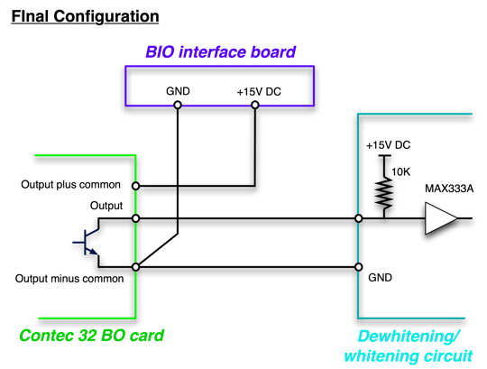
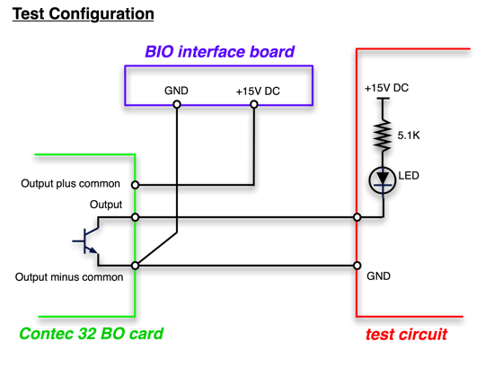
- A datasheet for the BO card is here attachment:contec32BO.pdf
Reflective Memory Network
- What is the temporary configuration ?
- What is the final configuration ?
Simulated Plant for Green locking
Conceptual Design


Model construction