
|
Size: 4934
Comment:
|
Size: 4956
Comment:
|
| Deletions are marked like this. | Additions are marked like this. |
| Line 116: | Line 116: |
| . To obtain a voltage signal, a pull-up resister and a DC voltage are needed because the signal is generated with a transistor. | . To obtain a voltage signal, a pull-up resister and a DC voltage are needed at the receiver stage because the signal is generated with a transistor. |
September CDS plan
Major Missions
 Complete damping of the vertex suspensions
 - Preparation for Green locking
- Simulated plants
Useful Links
category |
description |
Links |
plans and overviews |
CDS home page |
[:Upgrade_09/CDS] |
CDS plan for August |
[:Upgrade_09/CDS/August_CDS_test] |
|
Simulated Plant |
[:Simulated_Plant] |
|
Lists |
Current Hardware Lists |
[:Upgrade_09/CDS/current_hardware] |
Channel Assignments for C1SUS |
[:Upgrade_09/CDS/Suspension_wiring_to_channels] |
|
Technical Notes |
Notes about CDS realtime code |
[:Notes_on_getting_the_CDS_Realtime_Code_Generator_working] |
Notes for Green Locking interface to realtime code |
[:Notes_for_Green_locking_interface_to_RCG] |
|
Notes for Simulated Plant |
[:Notes_for_the_RCG_40m_simulated_plant] |
PLANS
TO DO LIST
attachment:green.png complete
attachment:orange.png intermediate state
attachment:red.png incomplete
attachment:black.png gave up
A. Complete suspension damping keeping in mind Version B coils. (1-2 days?)
ADC break out boards
- attachment:red.png design an adapter box for the breakout boards
- attachment:red.png make the box and install it
Binary Output working on c1sus (Alex/Joe) 1-2 days
- attachment:orange.png test all the BO channels and their assignments
- attachment:red.png Switching over cabling from the current XY220's to the new system
damping test with the BOs
- attachment:green.png damping all the vertex suspensions with the new CDS
- attachment:red.png check if the binary outputs are working
refinement of the control model
- attachment:red.png renewal of realtime control model
- attachment:red.png renewal of medm screens for the vertex suspensions
misc.
attachment:red.png fix feCodeGen.pl script
B. Preparation for Green Locking
Get RFM working (3-4 days)
- attachment:red.png make a new IPC parser
- attachment:green.png string the RFM optical fiber connecting C1SUS and C1ISCEX
- attachment:orange.png install PCI-5565 driver on c1sus
- attachment:red.png install PCI-5565 driver on c1iscex
- attachment:red.png test the RFM card by running the diagnostic script on the individually
- attachment:red.png test the RFM with the epics
Get both end stations working
- attachment:red.png Check we have correct number of cables (again tomorrow).
- attachment:red.png Check if both end stations are correctly running
Get IOO front end machine working
- attachment:red.png Move the computer into 1X2 rack
- attachment:red.png remove Marconi(?) and put a new IO chassis on 1X2 rack
- attachment:red.png check timing/ADC/DAC on the IO chassis. And make it works (5 days)
Fix non-working IO chassis
- attachment:red.png Check on fiber with Rolf for LSC
- attachment:red.png timing/ADC/DAC check
C. Simulated Plant
Simulated Green Locking
- attachment:red.png conceptual design
- attachment:red.png make realtime simlink model
- attachment:red.png compile and install the model
LSC simulated plant
- attachment:green.png conceptual design
- attachment:green.png make realtime simlink model
- attachment:orange.png compile and install the model
Gentoo patch (not high priority)
WISH LIST
(not urgent things, but somethings we want to implement at some points)
channel wiki
wiki hyperlink on a medm screen
TIME LINE SCHEDULE
- Put time line schedule here.
DETAILED CONSIDERATIONs
Cable Requirements
- Do we have sufficient number of the cables ?
- Let's doublecheck it.

Notes about Binary Outputs
- To obtain a voltage signal, a pull-up resister and a DC voltage are needed at the receiver stage because the signal is generated with a transistor.
- An easy way to check this BO system, one can put a LED as described in the figure below.
normal operation
test configuration
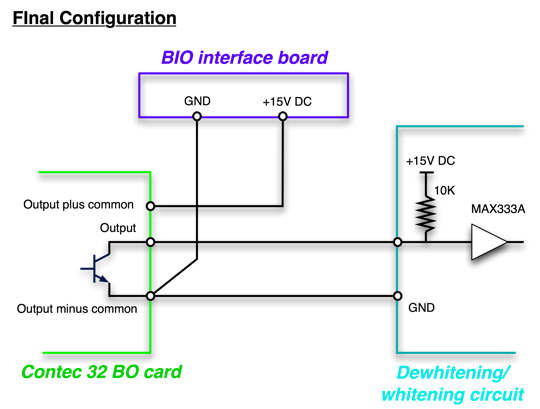
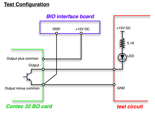
- A datasheet for the BO card is here attachment:contec32BO.pdf
Reflective Memory Network
- What is the temporary configuration ?
- What is the final configuration ?
Simulated Plant for Green locking
- Concept
- Model construction