
|
Size: 562
Comment:
|
Size: 7498
Comment:
|
| Deletions are marked like this. | Additions are marked like this. |
| Line 1: | Line 1: |
| August CDS Test(s) | ## page was renamed from Upgrade 09/CDS/August CDS test <<Anchor(TOP)>> = August CDS Tests = |
| Line 3: | Line 5: |
| The idea is test out the suspension controls for the vertex suspensions. This includes BS, PRM, SRM, ITMX, ITMY, MC1, MC2, and MC3. This is to replace the c1susvme1, c1susvme2, and c1sosvme machines with a single c1sus computer and IO chassis. | . The idea is test out the suspension controls for the vertex suspensions. This includes '''BS, PRM, SRM, ITMX, ITMY, MC1, MC2,''' and '''MC3'''. This is to replace the '''c1susvme1, c1susvme2, '''and '''c1sosvme machines''' with a single '''c1sus computer''' and '''IO chassis'''. |
| Line 5: | Line 7: |
| This requires switching over cabling from the current XY220's, Pentek ADCs and ICS 110Bs, and the Pentek DACs to our new system. | attachment:August_small.png |
| Line 7: | Line 9: |
| A wiring guide, to determine what plugs in where so we know what ADC/DAC/BO channels correspond can be found at: | --------- = Plan = == To do List == || attachment:green.png '''complete'''|| attachment:orange.png '''intermediate state ''' || attachment:red.png '''incomplete''' || attachment:black.png gave up|| . attachment:green.png Hardware installation . attachment:green.png installation of C1SUS and its settings . attachment:green.png mount the ADC/DAC/BIO boards and IO expansion chassis . attachment:green.png Order some cables . attachment:green.png list up the necessary cables . attachment:green.png order SCSIs . attachment:green.png order IDC40 flat cables and 37 pin D-sub male connecters . attachment:green.png order 3 pin power cables . {i} more information about the ordering are available [#ORDER here.] . attachment:green.png Make the cables . attachment:green.png 37 pin D-sub cables (3 meter long) . attachment:green.png three 37 pin D-sub female to 40 pin IDC cables (1.5 meter long) . attachment:green.png 3 pin power cables . '' we need some back shells for the connector heads'' . attachment:green.png Cable Inspection and Wiring . attachment:green.png draw a diagram for wiring . {i} the drawings can be found [#WIRING here] . attachment:green.png check DAC cable length . attachment:green.png check BO cable length . attachment:green.png Switching over cabling from the current XY220's, Pentek ADCs and ICS 110Bs, and the Pentek DACs to our new system. . attachment:green.png Develop the model files . attachment:green.png IOP file . attachment:green.png create (copy) the control model file . {i} [[Notes_on_getting_the_CDS_Realtime_Code_Generator_working]] . attachment:green.png make a list for channel assignment . {i} [[Upgrade 09/CDS/Suspension wiring to channels|ADC/DAC/BO channel assign list]] . attachment:green.png run the code . attachment:green.png fix the control model file if there are any bugs . attachment:orange.png timing/ADC/DAC/BO test . attachment:green.png timing board test . looks like running . attachment:green.png test all the ADC channels and their assignments . attachment:green.png test all the DAC channels and their assignments . attachment:orange.png test all the BO channels and their assingments . attachment:green.png Conversion of the filter coefficients . attachment:green.png copy the coefficients to the new CDS . attachment:green.png load the coefficients . Some notes are available [#COEFF here] . attachment:green.png Modification of AA filter box . attachment:green.png measure the box size . attachment:green.png order the box extension (or extension cables) . attachment:green.png install the extension . attachment:green.png Damping test of the suspensions . attachment:green.png PRM damping test . attachment:green.png All the suspension test . attachment:orange.png Test of the new Reflective Memory Network . attachment:green.png string the RFM optical fiber connecting C1SUS and C1ISCEX . attachment:orange.png install PCI-5565 driver . attachment:orange.png test the RFM card by running the diagnostic script on the individually . attachment:orange.png test the RFM with the epics [[BR]] [[BR]] == Timeline Schedule == . The table below shows the timeline schedule of this test. It ends at 13th August ideally. . attachment:timeline.png [[BR]] [[BR]] --------- = Detailed Considerations = == Channel Assignment and Model files == . A wiring guide, to determine what plugs in where so we know what ADC/DAC/BO channels correspond can be found at: |
| Line 9: | Line 96: |
||<:> ''' IOP model ''' ||<:> ''' C1SUS model'''|| || attachment:coming_soon.png || attachment:c1sus_mdl.png || [[BR]] [[BR]] <<Anchor(WIRING)>> == Suspension wiring == . Basically all the cables for the ADCs and DACs are no ||<:> ''' Current Wiring Setup ''' ||<:> ''' New Wiring Plan ''' ||<:> ''' Missing stuff as of Aug.3rd''' || || <<ImageLink(sus_wiring.png, /Electronics/1Y4/Suspension_Wiring)>> ||<<ImageLink(sus_new_wiring.png, /Electronics/1Y4/Suspension_new_Wiring)>> || <<ImageLink(sus_missing_stuff.png, Electronics/1Y4/Suspension_new_Wiring)>>|| [attachment:suspension_wiring_graffle.zip Zipped original drawing file written in Omnigraffle] [[BR]] [[BR]] <<Anchor(COEFF)>> == Conversion of the filter coefficients == . To convert the filter coefficients the filter files that live in . {{{ /cvs/cds/rtcds/caltech/c1/chans}}} . should be updated. The {{{ C1***.txt}}} file contains all the filters (originally empty). . In order to transport the coefficients from the old front end machines, we need to look at the files in . {{{ /cvs/cds/caltech/chans/ }}} . and port over the approriate filters to {{{C1***.txt}}}. [[BR]] [[BR]] --------- <<Anchor(ORDER)>> = Information about ordering and Cable Standards = == SCSIs cables == . A SCSI type called ''' HD 68 (High Density 68 pin)''' is used. It's sometimes categorized as a D-sub because it has a D-shape at the end. The table below is the status of the ordering || ''' description''' || '''part number '''|| '''vender''' || '''price'''|| '''Qty.''' ||'''notes''' || '''status'''|| || 15m SCSI HD68 Differential M/M cable|| 328215-003 ||Hewlett-Packard (made by Amphenol) || $|| 1 || Differential type. takes five days || attachment:green.png ordered Aug.5 || || 2.5m SCSI HD68 M/M cable || C2911C || Hewlett-Packard ||$ || 8 || takes five days || attachment:green.png ordered Aug.5 || || 1.5m SCSI HD68 M/M cable || C2924C ||Hewlett-Packard || $|| 14|| takes five days || attachment:green.png ordered Aug.5 || == 37 pin D-sub == . The type of the flat cables is '''IDC 40 ''' which has a conductor pitch of , and AWG of . || ''' description''' || '''part number '''|| '''vender''' || '''price'''|| '''Qty.''' ||'''notes''' || '''status'''|| || 37 pin female connector || 1658613-1 || Tyco Electronics|| $ || 20 || takes a day || attachment:green.png ordered Aug.5|| || IDC 40 flat cable || 135-2801-040 ||Amphenol || $ || 1 || takes a day || attachment:green.png ordered Aug.5 || == 3 pin power cable for the Binary I/O board == || ''' description''' || '''part number '''|| '''vender''' || '''price'''|| '''Qty.''' ||'''notes''' || '''status'''|| || 3 conductor cable || 602-65403 || Mouser Electronics || $ || 1 || takes a day || attachment:green.png ordered Aug.5 || || back shell || || || || ~ 100 || not so urgent || attachment:red.png will be ordered || || SOCKET COMBO-D 12-14AWG SLD|| 132C10029X || CONEC|| $ || || <<ImageLink(solderpin.jpg, void,width=80)>> || order some if necessary || || D-sub solder cup female || 3003W3SXX42A10X || CONEC || $ || || <<ImageLink(3pinsocket.jpg, http://www.conec.com/catalogs/c1/ioconnector/catalog/product/view/id/491,width=150)>> [attachment:3003W3SXX42A10X.pdf drawing]|| order some if necessary || [[BR]] [[BR]] --------- = Links = . [#TOP back to page top ] . [[Upgrade_09/CDS|new CDS page]] . [[Electronics|Electronics page]] . [:Upgrade_09/CDS/September_CDS_plan] [[BR]] [[BR]] |
August CDS Tests
The idea is test out the suspension controls for the vertex suspensions. This includes BS, PRM, SRM, ITMX, ITMY, MC1, MC2, and MC3. This is to replace the c1susvme1, c1susvme2, and c1sosvme machines with a single c1sus computer and IO chassis.
attachment:August_small.png
Plan
To do List
attachment:green.png complete |
attachment:orange.png intermediate state |
attachment:red.png incomplete |
attachment:black.png gave up |
- attachment:green.png Hardware installation
- attachment:green.png installation of C1SUS and its settings
- attachment:green.png mount the ADC/DAC/BIO boards and IO expansion chassis
- attachment:green.png Order some cables
- attachment:green.png list up the necessary cables
- attachment:green.png order SCSIs
- attachment:green.png order IDC40 flat cables and 37 pin D-sub male connecters
- attachment:green.png order 3 pin power cables
 more information about the ordering are available [#ORDER here.]
- attachment:green.png Make the cables
- attachment:green.png 37 pin D-sub cables (3 meter long)
- attachment:green.png three 37 pin D-sub female to 40 pin IDC cables (1.5 meter long)
- attachment:green.png 3 pin power cables
we need some back shells for the connector heads
- attachment:green.png Cable Inspection and Wiring
- attachment:green.png draw a diagram for wiring
- the drawings can be found [#WIRING here]
- attachment:green.png check DAC cable length
- attachment:green.png check BO cable length
- attachment:green.png Switching over cabling from the current XY220's, Pentek ADCs and ICS 110Bs, and the Pentek DACs to our new system.
- attachment:green.png draw a diagram for wiring
- attachment:green.png Develop the model files
- attachment:green.png IOP file
- attachment:green.png create (copy) the control model file
- attachment:green.png make a list for channel assignment
- attachment:green.png run the code
- attachment:green.png fix the control model file if there are any bugs
- attachment:orange.png timing/ADC/DAC/BO test
- attachment:green.png timing board test
- looks like running
- attachment:green.png test all the ADC channels and their assignments
- attachment:green.png test all the DAC channels and their assignments
- attachment:orange.png test all the BO channels and their assingments
- attachment:green.png timing board test
- attachment:green.png Conversion of the filter coefficients
- attachment:green.png copy the coefficients to the new CDS
- attachment:green.png load the coefficients
- Some notes are available [#COEFF here]
- attachment:green.png Modification of AA filter box
- attachment:green.png measure the box size
- attachment:green.png order the box extension (or extension cables)
- attachment:green.png install the extension
- attachment:green.png Damping test of the suspensions
- attachment:green.png PRM damping test
- attachment:green.png All the suspension test
- attachment:orange.png Test of the new Reflective Memory Network
- attachment:green.png string the RFM optical fiber connecting C1SUS and C1ISCEX
- attachment:orange.png install PCI-5565 driver
- attachment:orange.png test the RFM card by running the diagnostic script on the individually
- attachment:orange.png test the RFM with the epics
Timeline Schedule
- The table below shows the timeline schedule of this test. It ends at 13th August ideally.
- attachment:timeline.png
Detailed Considerations
Channel Assignment and Model files
- A wiring guide, to determine what plugs in where so we know what ADC/DAC/BO channels correspond can be found at:
IOP model |
C1SUS model |
attachment:coming_soon.png |
attachment:c1sus_mdl.png |
Suspension wiring
- Basically all the cables for the ADCs and DACs are no
Current Wiring Setup |
New Wiring Plan |
Missing stuff as of Aug.3rd |
|
|
|
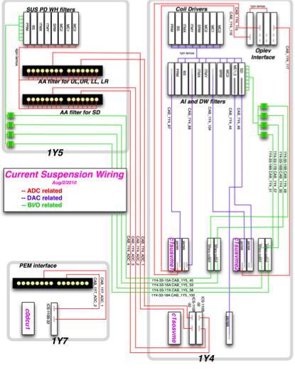

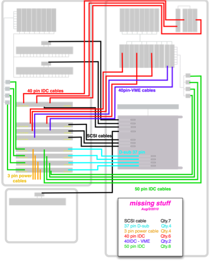
[attachment:suspension_wiring_graffle.zip Zipped original drawing file written in Omnigraffle] BR BR
Conversion of the filter coefficients
- To convert the filter coefficients the filter files that live in
/cvs/cds/rtcds/caltech/c1/chans
should be updated. The C1***.txt file contains all the filters (originally empty).
- In order to transport the coefficients from the old front end machines, we need to look at the files in
/cvs/cds/caltech/chans/
and port over the approriate filters to C1***.txt.
Information about ordering and Cable Standards
SCSIs cables
A SCSI type called HD 68 (High Density 68 pin) is used. It's sometimes categorized as a D-sub because it has a D-shape at the end.
The table below is the status of the ordering
description |
part number |
vender |
price |
Qty. |
notes |
status |
15m SCSI HD68 Differential M/M cable |
328215-003 |
Hewlett-Packard (made by Amphenol) |
$ |
1 |
Differential type. takes five days |
attachment:green.png ordered Aug.5 |
2.5m SCSI HD68 M/M cable |
C2911C |
Hewlett-Packard |
$ |
8 |
takes five days |
attachment:green.png ordered Aug.5 |
1.5m SCSI HD68 M/M cable |
C2924C |
Hewlett-Packard |
$ |
14 |
takes five days |
attachment:green.png ordered Aug.5 |
37 pin D-sub
The type of the flat cables is IDC 40 which has a conductor pitch of , and AWG of .
description |
part number |
vender |
price |
Qty. |
notes |
status |
37 pin female connector |
1658613-1 |
Tyco Electronics |
$ |
20 |
takes a day |
attachment:green.png ordered Aug.5 |
IDC 40 flat cable |
135-2801-040 |
Amphenol |
$ |
1 |
takes a day |
attachment:green.png ordered Aug.5 |
3 pin power cable for the Binary I/O board
description |
part number |
vender |
price |
Qty. |
notes |
status |
3 conductor cable |
602-65403 |
Mouser Electronics |
$ |
1 |
takes a day |
attachment:green.png ordered Aug.5 |
back shell |
|
|
|
~ 100 |
not so urgent |
attachment:red.png will be ordered |
SOCKET COMBO-D 12-14AWG SLD |
132C10029X |
CONEC |
$ |
|
|
order some if necessary |
D-sub solder cup female |
3003W3SXX42A10X |
CONEC |
$ |
|
|
order some if necessary |


Links
- [#TOP back to page top ]
- [:Upgrade_09/CDS/September_CDS_plan]