|
Size: 9179
Comment:
|
Size: 10475
Comment:
|
| Deletions are marked like this. | Additions are marked like this. |
| Line 103: | Line 103: |
| * Design the platform to place two aLIGO OMCs and some optical mounts. The optical layout has already been done by KA with AutoCAD (2D). This needs to be turned to 3D in SolidWorks. The board is a relatively a big component. Upon designing, the procedure for the installation needs to be considered too. |
|
| Line 104: | Line 106: |
| * Procurement/C&B and assembly of the BHD Board. |
|
| Line 105: | Line 109: |
| * BHD Board will have some off-the-shelf in-vacuum optical mounts including picomotor control for the BHD BS. They need to be procured. Are they compatible with the 40m vacuum without any cleaning/modification? |
|
| Line 106: | Line 112: |
| * We will use the aLIGO OMCs for the experiment. To complete the 4th OMC, some small sub-assy components need to be procured. Procure the components interface with Stephen who has the list of the missing components and knows what is what. * We might need to use some help from CDS (Rich/Chub) for the cabling/connectors. |
|
| Line 110: | Line 118: |
| * Check if we need additional in DB25 vac cable stands. * What about invac DB25 cables? |
|
| Line 112: | Line 122: |
| * Design and fabricate the optical baffles for the arm cavity and also the vertex/BHD optics. | |
| Line 114: | Line 125: |
| * The current optical layout has been designed with AutoCAD. * We have an incomplete SoildWorks model of the 40m. Complete the model and also populate it with the mechanical/opto-mechanical components. |
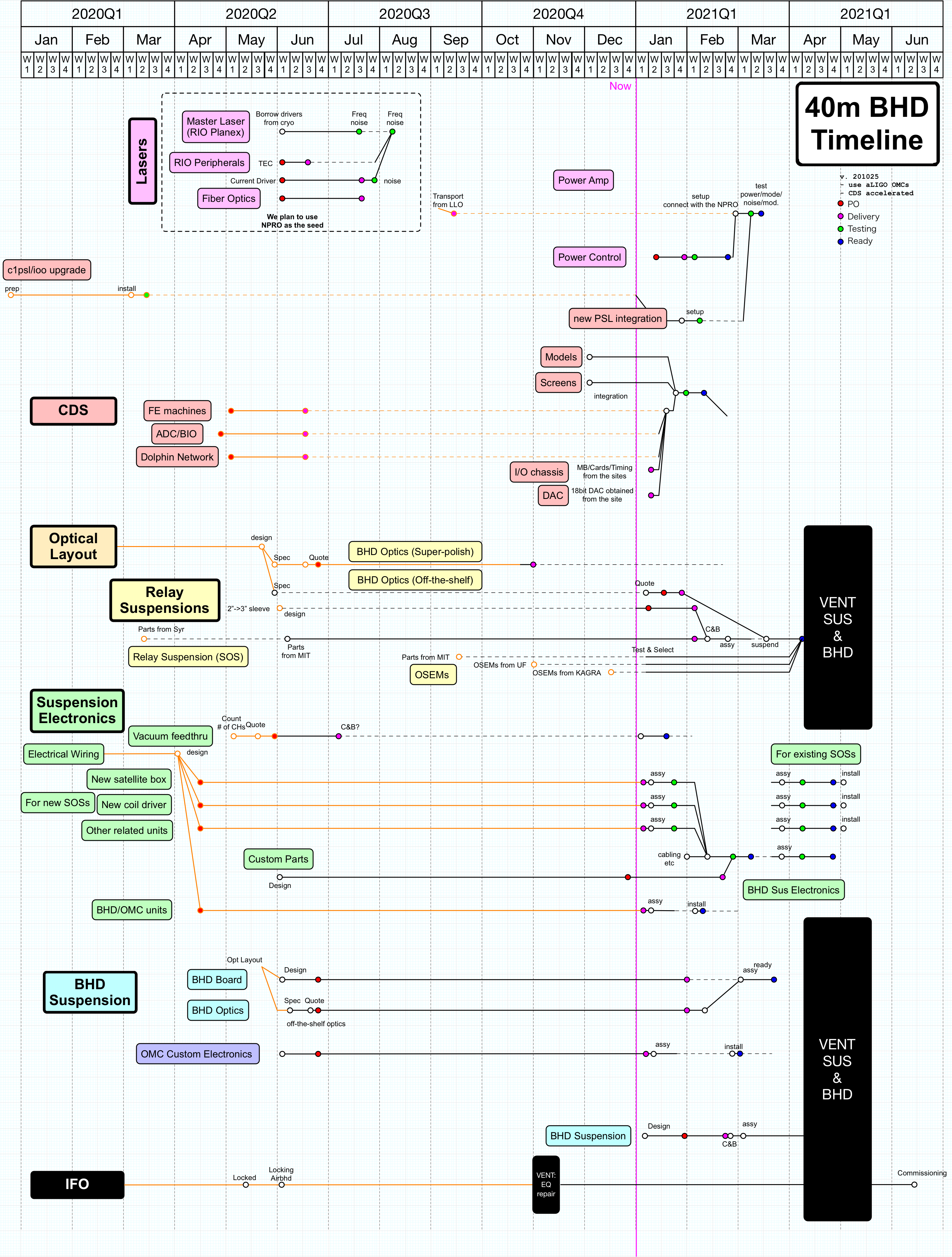
Tasks leading up to the BHD experiment at the 40m meter are briefly described here. Please keep this page up to date with any info that makes the tasks more descriptive (i.e. minimal private communications). See this google spreadsheet for task allocation and rough deadlines.
Contents
1. CDS
1.1. Test of new FEs
The BHD upgrade will require two new FE machines to be installed. Additionally, the old SunFire server machine for c1ioo will be replaced with a more modern SuperMicro version. We'd like to test this infrastructure ASAP. Steps involved are:
Procure 3 SuperMicro servers with compatible motherboard and sufficient PCIe slots.
- Procure OSSI PCIe expansion card (server side, minimum 2 pcs, preferably 3). We have the cards for the expansion chassis side in hand already.
Procure 2 aLIGO timing interface units (chassis side) consisting of D070071, D080335, and D0902184-v2.
- Install OSSI PCIe expansion card and Dolphin card, and set them up for diskless boot over the martian network.
- Connect to the DAQ network, Dolphin network.
- Install expansion chassis and connect timing interface, timing signal via fiber from Timing Fanout in 1X6. Then connect to host machine.
- Install test ADC, DAC and BIO cards in the expansion chassis. Run some diagnostic tests with a test realtime model (just loopback a DAC signal read back by ADC? Or something more sophisticated? Any checksum based tests for the IPC?).
1.2. Phasing out of RFM in favor of Dolphin
We'd like to transfer the two end machines onto the Dolphin network for IPC (in favor of the RFM network they're currently on). For testing:
Install a Dolphin card (in hand) in the server machine for c1iscex.
Connect c1iscex to the Dolphin network.
Confirm that the same signals that are sent over the RFM network are received over the Dolphin network (how? checksum? may have to account for clock cycle delays from the c1rfm model).
1.3. RT models and MEDM screen for BHD
- Need new MEDM screens for new suspensions (almost done).
Closely related to Mechanics. Suspension models can be set up as the new suspensions are assembled, and we can run CDS tests (e.g. OSEM diagonalization, actuator calibration etc etc). This is pretty easily done once we have the new machines set up.
1.4. Phase out VME crate at EY in favor of Acromag
- Acromag chassis needs to be assembled and wired.
- Individual Acromag units need to be configured for the internal subnet.
- A supermicro server machine needs to be set up.
- A database file needs to be prepared.
- Care will have to be taken in the wiring not to worsen the grounding situaiton.
- Once bench tests pass, we can install this in 1Y4.
2. Mechanics
2.1. SOS
We use total 17 Small Optics Suspensions (SOSs). 10 SOSs (MC1/2/3, PRM/SRM/BS, ITMX/ITMY, ETMX/ETMY) were already installed and 7 more SOSs (PR2/3, SR2, AS1/2, LO1/2) are going to be newly installed.
SOS Parts status (SUS/Mechanics Tab): https://docs.google.com/spreadsheets/d/1lXCG_viFQnxueJS3KlBEzR3tadrxox27aV5WT7jczO4/edit#gid=522038028
2.1.1. SOS Disassembly / C&B
- We have partial SOS assemblies collected from MIT/Syracuse. (See above spreadsheet)
Disassemble them and put them in a C&B queue.
2.1.2. SOS missing parts procure / C&B
- The above spreadsheet specifies how many we do have to procure for each component.
Procure the missing parts and put them in a C&B queue.
2.1.3. SOS new (improved) parts
- The legacy SOS is not the best suspension to handle. Once we find a good solution to make it better we need to fabricate the components for all 17 suspensions. (But this does not mean we will replace all the parts during the vent.)
- One problem is that the earthquake (EQ) stops are not well visible and difficult to handle. The most painful one to handle is the bottom four EQ stops. Their diameter is small and difficult to turn with fingers. One possibility is to move the adjusting screw to the front or back faces using a pivoting mechanism. Or maybe we just replace these four with two 1/4-20 EQ stops. We never leave a mirror on the EQ stops as they are not a stable holder for a mirror in any configuration.
2.1.4. SOS 2" -> 3" sleeve design
The 7 new SOSs suspends 2" optics in 2"->3" sleeves.
Draft version of the sleeve has already been made by Koji in SolidWorks.
The model and related parts can be found under the box folder of the 40m as /40m/40m_cad_models/SmallOpticSuspension/Solildworks/SOS_2inch_optic_Test_Mass_ASSY.SLDASM
- Tasks:
- Check the center of mass (CoM) - already assigned to Jordan
The optics have a thickness of 3/8". Just in case, we should check the actual size with the datasheets and the delivered optics. (Lambda optics / Five Nine Optics / G&H optics) -> Optics section
- The CoM should be in the same plane of the wires. With the default design how much is the gap and in which direction? Can we fix the gap by a thin PTFE shim, for example?
- We should be able to adjust the pitching of the optic by the balance mass at the bottom. How much is the adjustment range?
The height of the CoM needs to be check and adjusted. The CoM has to be 0.9mm below the clamping point of the wires (cf https://dcc.ligo.org/DocDB/0028/T970135/000/T970135-02.pdf). This ensures the pitching resonant frequency to be ~0.6Hz. But this frequency needs to be checked in the model.
- Make the 2D parts drawings from the 3D parts. Upon making the 2D parts, practical features like chamfer etc should be added.
- Material choice: The big ring should be Al. And the mirror stoppers are PEEK or PTFE. What about the others? (Calum may have an opinion about it.)
- Is there any modification to make the sleeve more reasonable?
- Cap screws are used for fastening the side clamps to give stronger torque. But this made the side magnet(s) to be stick out more. Are button head screws better?
- The bottom pitch adjuster is fixed by a set screw at the bottom. But this requires us to lift the mass to access the bottom set-screw or just go beneath the mirror in the suspension to fasten it. Is there any better idea to fix the adjuster from the front or back?
- Check the center of mass (CoM) - already assigned to Jordan
2.1.5. SOS 2" -> 3" sleeve procurement / C&B
Along with the above design, procure the actual parts and put them in C&B queues.
2.1.6. SOS Assembly
- Assemble new SOSs
- Suspend the metal sleeve + optic with steel wires
- Adjust the alignment of the suspended optic using an optical lever (in the 40m clean room)
2.1.7. SOS OSEM Test
Each SOS needs 5 OSEMs -> In total we need 35 OSEMs
- We collected large number of OSEMs and OSEM parts from MIT, UF, KAGRA, and CIT.
- First we check the completed OSEMs with regard to its electrical properties (Coil L and R), and then check the LED/PD functionalities (light level, alignment/uniformity). If necessary, install optical filter to cut 1064nm.
- If the number of the healthy OSEMs are more than 35+some spare, it's done. If not, assemble some more OSEMs and make the above test.
2.1.8. SOS In-air Tests
- Check some basic SOS functionality (resonant freq, actuation matrix, sensing characteristicss, etc) in air using CDS.
2.2. BHD Board
2.2.1. BHD Board Design
Design the platform to place two aLIGO OMCs and some optical mounts. The optical layout has already been done by KA with AutoCAD (2D). This needs to be turned to 3D in SolidWorks. The board is a relatively a big component. Upon designing, the procedure for the installation needs to be considered too.
2.2.2. BHD Board Procure / Assy
Procurement/C&B and assembly of the BHD Board.
2.2.3. BHD Board Off-the-shelf mounts Procure
- BHD Board will have some off-the-shelf in-vacuum optical mounts including picomotor control for the BHD BS. They need to be procured. Are they compatible with the 40m vacuum without any cleaning/modification?
2.2.4. OMC Small components Procure/C&B/Assy
- We will use the aLIGO OMCs for the experiment. To complete the 4th OMC, some small sub-assy components need to be procured. Procure the components interface with Stephen who has the list of the missing components and knows what is what.
- We might need to use some help from CDS (Rich/Chub) for the cabling/connectors.
2.3. Misc Mechanics
2.3.1. Other small in-vac components
- Check if we need additional in DB25 vac cable stands.
- What about invac DB25 cables?
2.3.2. Light Baffles
- Design and fabricate the optical baffles for the arm cavity and also the vertex/BHD optics.
2.3.3. 40m Solidworks Model
- The current optical layout has been designed with AutoCAD.
We have an incomplete SoildWorks model of the 40m. Complete the model and also populate it with the mechanical/opto-mechanical components.
3. Optics
3.1. BHD Off-the-shelf optics
3.2. OMC assy
3.3. Lambda Optics Characterization
3.4. Surveying / Ranging optics' distances
4. Electronics
4.1. Electronics chain for 1 suspension
First, we will test the electronics chain for 1 (non test-mass type) suspension, say MC1.
- HAM-A Coil driver (2pcs)
- Satellite box (1pc)
- Interface cabling to connect to CDS system.
- Install electronics once they've passed bench test (TFs, noise).
- Re-calibrate CDS settings (damping gains, whitening etc) for the new electronics.
- Observe over some weeks for stability/problems.
4.2. Suspension electronics overhaul
Once we are happy with 1 suspension, we will need to repeat for all the remaining 9 SOS installed, and also prepare for the 7 SOS to be installed. This phase will be a bit more involved. Will also require AA/AI/ISC whitening boards to be prepared. It will also require the HV coil driver to be prepared and tested.
4.3. OMC electronics
5. Vent
Unless there's a good reason, we will not vent the system and modify the core IFO layout until we have all the necessary pieces in hand and tested (including OMCs, BHD breadboard etc).
6. Timeline