
|
Size: 4980
Comment:
|
← Revision 98 as of 2018-07-30 17:48:17 ⇥
Size: 6419
Comment:
|
| Deletions are marked like this. | Additions are marked like this. |
| Line 1: | Line 1: |
| ## page was renamed from Upgrade 09/Optical Layout | |
| Line 4: | Line 5: |
| == Overview == | == Optical Layout plan == === Vent Aug 04, 2011 === The new layout as of vent on Aug 04, 2011 [[https://dcc.ligo.org/cgi-bin/private/DocDB/ShowDocument?docid=98061]] == Archive of the previous layouts == === Vent Dec 18, 2010 === |
| Line 9: | Line 19: |
| This corresponds to the cavity lengths of PRC: 6.773 m / SRC: 5.419 m {i} The arm cavity cause a small phase shift depending on its resonant (or say, non-resonant) condition. If we assume the arm length of 38.4 m, we get corrections of the length * '''PRC: 6.7466 m''' * '''SRC: 5.4798 m''' |
This corresponds to the cavity lengths of about 6.8 m and 5.4 m for the PRC and SRC, respectively. For the correct amount of those lengths, visit [[IFO_Modeling]] pages. |
| Line 22: | Line 28: |
| == New Optical Layout plan == '''[Latest]''' The new optical layout plan as of May 06, 2010. |
The optical layout plan as of Dec 18, 2010. This reflects the latest installation of the optics in the vacuum chambers. |
| Line 25: | Line 30: |
| attachment:100506_40m_upgrade_layout.pdf | [[attachment:101218_40m_upgrade_layout.pdf]] |
| Line 27: | Line 32: |
| <<ImageLink(100506_40m_upgrade_layout-ALL.png, Upgrade 09/Optical Layout,width=400)>><<ImageLink(100506_40m_upgrade_layout-OMC.png, Upgrade 09/Optical Layout,width=400)>><<ImageLink(100506_40m_upgrade_layout-IMC.png, Upgrade 09/Optical Layout,width=400)>><<ImageLink(100506_40m_upgrade_layout-BSC.png, Upgrade 09/Optical Layout,width=400)>><<ImageLink(100506_40m_upgrade_layout-ITMX.png,Upgrade 09/Optical Layout,width=400)>><<ImageLink(100506_40m_upgrade_layout-ITMY.png,Upgrade 09/Optical Layout,width=400)>><<ImageLink(100506_40m_upgrade_layout-ETMX.png,Upgrade 09/Optical Layout,width=400)>><<ImageLink(100506_40m_upgrade_layout-ETMY.png,Upgrade 09/Optical Layout,width=400)>>The meain beam (red) and the pick-off beams (pale blue) indicated by three parallel lines has 18mm diameter. This indicates 6w, where w is the beam radius. The waist size of the arm cavity is about 3mm (1/e^2 radius) and the Rayleigh range is about 27m. | The main beam (red) and the pick-off beams (pale blue) indicated by three parallel lines has 18mm diameter. This indicates 6w, where w is the beam radius. The waist size of the arm cavity is about 3mm (1/e^2 radius) and the Rayleigh range is about 27m. |
| Line 29: | Line 34: |
| '''- To Do:''' * PRM/SRM/BS/ETMs wedge arrangements and reflections * Video: check view angles * Work at around OMC |
- To Do: |
| Line 35: | Line 37: |
| == Archive of the previous layouts == | |
| Line 37: | Line 39: |
| Previous optical layout by Y. Aso, attachment:40mUpgradeOpticalLayoutPlan01.pdf Zoom of the optical layout by Y. Aso, attachment:layout-zoom.pdf | Previous optical layout by Y. Aso, [[attachment:40mUpgradeOpticalLayoutPlan01.pdf]] Zoom of the optical layout by Y. Aso, [[attachment:layout-zoom.pdf]] |
| Line 50: | Line 52: |
| attachment:40m_opt_layout_Orig_with_comment.pdf | [[attachment:40m_opt_layout_Orig_with_comment.pdf]] |
| Line 53: | Line 55: |
| Here is the Mathematica notebook I wrote to calculate various parameters for the new recycling cavities.[attachment:NewRecyclingCavities.zip attachment:NewRecyclingCavities.zip] The PDF version is here: [attachment:NewRecCav.pdf attachment:NewRecCav.pdf] [attachment:GaussianOpticsTutorial.pdf attachment:GaussianOpticsTutorial.pdf] | Here is the Mathematica notebook I wrote to calculate various parameters for the new recycling cavities.[[attachment:NewRecyclingCavities.zip|attachment:NewRecyclingCavities.zip]] The PDF version is here: [[attachment:NewRecCav.pdf|attachment:NewRecCav.pdf]] [[attachment:GaussianOpticsTutorial.pdf|attachment:GaussianOpticsTutorial.pdf]] |
| Line 57: | Line 59: |
| '''Note: This calculation does not include the effect of the arm cavity. Thus the length of the cavities are slightly different from the actual desired values.''' |
|
| Line 58: | Line 62: |
| <<Anchor(wedge)>>All of the main optics have wedge angles of several degrees in order to avoid undesirable interference of back-surface reflections into the main beam. Because of these wedges, we need to design the optical path slightly shifted from the normal angles.In order to incorporate the effect of the wedges, a Mathematica code to calculate the beam deflections has been developed. attachment:wedge_analysis.nb During the installation we like to align the beam spot onto ETMs while the beam goes through the center of ITMs. However, if we put the actual ITMs at their correct positions, we will not be able to see the spot at the end. If we remove the ITMs, the deflection of the beam is not provided, and the correct alignment is not obtained.One possible solution is to put a wedged plate which has no coating. If the wedge angle is the same as the final optics, the resulting beam has the desired deflection angle. Even though the difference of the thickness shifts the beam in parallel, the amount of shift is small and will not be a significant problem. The multiple reflections will allow us to align the pick off beams as well. The candidate of the wedge plates are: attachment:ITMY_wedge_1deg.png [attachment:wedge.pdf attachment:wedge.pdf] | <<Anchor(wedge)>> All of the main optics have wedge angles of several degrees in order to avoid undesirable interference of back-surface reflections into the main beam. Because of these wedges, we need to design the optical path slightly shifted from the normal angles.In order to incorporate the effect of the wedges, a Mathematica code to calculate the beam deflections has been developed. [[attachment:wedge_analysis.nb]] {{attachment:ITMY_wedge_1deg.png}} [[attachment:wedge.pdf|attachment:wedge.pdf]] <<Anchor(PR3SR3)>> = ► Issues related to the replacement of PR3 and SR3 (plan) = It turns out that we need to move the position of the periscope to accommodate some beam dumps for the green light. Some details are described in this section. == Proposed Optical layout for PR3 region == We will replace the PR3 mirror by a better dichroic mirror to get more power in the transmitted green light. At the same time, in order to avoid unwanted ghost beams due to the transmission through PR3, an wedge angle of 2 deg has been proposed. However on the other hand, it turned out that we need to make some space to accommodate beam dumps. The attached picture below shows the proposed optical layout around the PR3 region. * PR3 -- remains at the same position. * TFP-532-56 (PBS) -- remains at the same position. * periscope -- needs to be go toward the MC side, however the periscope is already on the edge of the optical table. * a solution is to install a table extension to allow the periscope to go further. * beam dumps -- we will newly install two of them. * Another advantage of the table extension -- There is a hole just underneath where the PBS stands (it's not shown in the attached layout). * A table expansion can cover the hole. {{ attachment:PR3.png }} . [[ attachment:PR3_layout.pdf | in pdf style with finer resolution]] . [[ attachment:PR3_layout.zip | omnigraffle]] == Proposed Optical layout for SR3 region == Also for the same reason, we will replace the SR3 mirror too. Unlike the PR3 situation, there looks plenty of space. Therefore we don't have to do some special treatment for this. The picture below shows the proposed optical layout around the SR3 region. * SR3 -- remains at the same position. * Y2-2050 --- remains at the same position. * beam dump -- we will newly install one. {{ attachment:SR3.png }} . [[ attachment:SR3_layout.pdf | in pdf style with finer resolution]] . [[ attachment:SR3_layout.zip | omnigraffle]] = ►Vacuum Chamber Pictures = == ITMY 06/22/2018 == [[attachment:ITMY5.jpg|{{attachment:ITMY5.jpg||width=600}}]] [[attachment:ITMY1.jpg|{{attachment:ITMY1.jpg||width=600}}]] [[attachment:ITMY3.jpg|{{attachment:ITMY3.jpg||width=600}}]] == ETMY 06/22/2018 == [[attachment:ETMY1.jpg|{{attachment:ETMY1.jpg||width=600}}]] [[attachment:ETMY2.jpg|{{attachment:ETMY2.jpg||width=600}}]] = Vacuum Window Coating Nov 11, 2001 = [[attachment:Vacuum Window Coatings 2001|{{attachment:BK7windowCoatings.pdf.PDF||width=600}}]] |
Contents
►Change in the optical layout
Optical Layout plan
Vent Aug 04, 2011
The new layout as of vent on Aug 04, 2011
https://dcc.ligo.org/cgi-bin/private/DocDB/ShowDocument?docid=98061
Archive of the previous layouts
Vent Dec 18, 2010
The major change in the optical layout is the change of the cavity lengths for PRC and SRC. Since the modulation frequencies of 11MHz and 55MHz are used for the control of the interferometer, the lengths of PRC and SRC are significantly streched.
The actual modulation frequency is 11.065399MHz and its integer multiples. (based on the measurement of the MC length on 29th Sept, 2009)
This corresponds to the cavity lengths of about 6.8 m and 5.4 m for the PRC and SRC, respectively. For the correct amount of those lengths, visit IFO_Modeling pages.
These cavity lengths result in numbers of modifications in the optical configuration:
- In order to accomodate longer PRC and SRC, they have to be folded across the several optical tables.
- The curvature radii of PRM and SRM are recalculated accordingly.
- We are going to employ 2inch flat folding mirrors suspended with Enhanced LIGO/Advanced LIGO style Tip-Tilt suspensions with passive damping using eddy current.
The optical layout plan as of Dec 18, 2010. This reflects the latest installation of the optics in the vacuum chambers.
The main beam (red) and the pick-off beams (pale blue) indicated by three parallel lines has 18mm diameter. This indicates 6w, where w is the beam radius. The waist size of the arm cavity is about 3mm (1/e^2 radius) and the Rayleigh range is about 27m.
- To Do:
- Output MMT
- Previous layouts by Y. Aso
Previous optical layout by Y. Aso, 40mUpgradeOpticalLayoutPlan01.pdf Zoom of the optical layout by Y. Aso, layout-zoom.pdf
The CAD files canbe found in /cvs/cds/caltech/users/aso/doc/CAD40m/2D/40mUpgradeOpticalLayoutSRMinITMX.dwb
This is VariCAD file. VariCAD is installed on rosalba and allegra.
*** Now KA switched from VariCAD/dwb to AutoCAD/dwg based work. Reason:
- The original AutoCAD file is provided by M. Smith.
During the dwg->dwb conversion, a lot of information is lost.
- Because of this, it turned out (for KA) that precise work in VariCAD is totally difficult.
- Layer function of VariCAD is too weak to work with.
- RSE layout by M. Smith
40m_opt_layout_Orig_with_comment.pdf
►Radii of curvature
Here is the Mathematica notebook I wrote to calculate various parameters for the new recycling cavities.attachment:NewRecyclingCavities.zip The PDF version is here: attachment:NewRecCav.pdf attachment:GaussianOpticsTutorial.pdf
This notebook explains how the cavity lengths, recycling mirror ROCs, PRM reflectivity are chosen.
Note: This calculation does not include the effect of the arm cavity. Thus the length of the cavities are slightly different from the actual desired values.
►Effect of the wedge
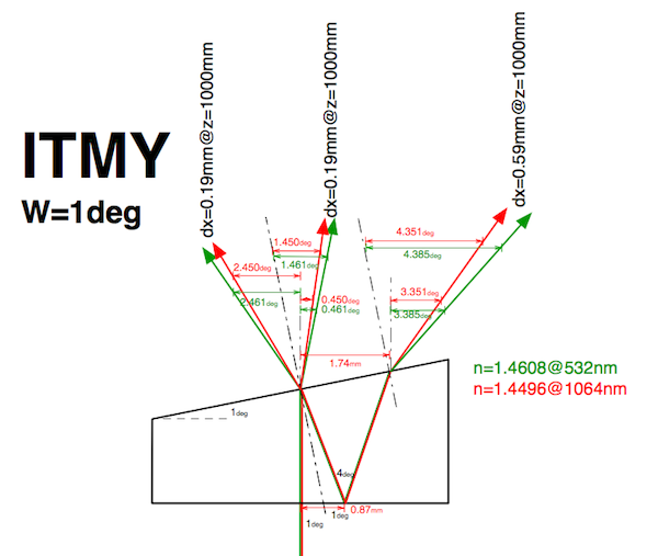
All of the main optics have wedge angles of several degrees in order to avoid undesirable interference of back-surface reflections into the main beam. Because of these wedges, we need to design the optical path slightly shifted from the normal angles.In order to incorporate the effect of the wedges, a Mathematica code to calculate the beam deflections has been developed. wedge_analysis.nb
► Issues related to the replacement of PR3 and SR3 (plan)
It turns out that we need to move the position of the periscope to accommodate some beam dumps for the green light. Some details are described in this section.
Proposed Optical layout for PR3 region
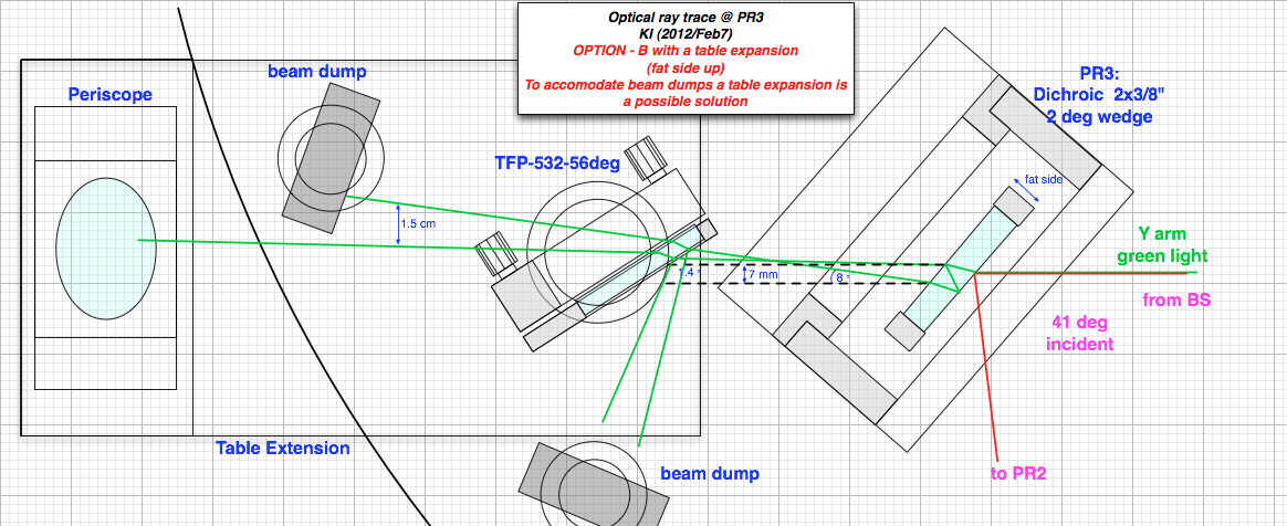
We will replace the PR3 mirror by a better dichroic mirror to get more power in the transmitted green light. At the same time, in order to avoid unwanted ghost beams due to the transmission through PR3, an wedge angle of 2 deg has been proposed. However on the other hand, it turned out that we need to make some space to accommodate beam dumps.
- The attached picture below shows the proposed optical layout around the PR3 region.
- PR3 -- remains at the same position.
- TFP-532-56 (PBS) -- remains at the same position.
- periscope -- needs to be go toward the MC side, however the periscope is already on the edge of the optical table.
- a solution is to install a table extension to allow the periscope to go further.
- beam dumps -- we will newly install two of them.
- Another advantage of the table extension -- There is a hole just underneath where the PBS stands (it's not shown in the attached layout).
- A table expansion can cover the hole.
Proposed Optical layout for SR3 region
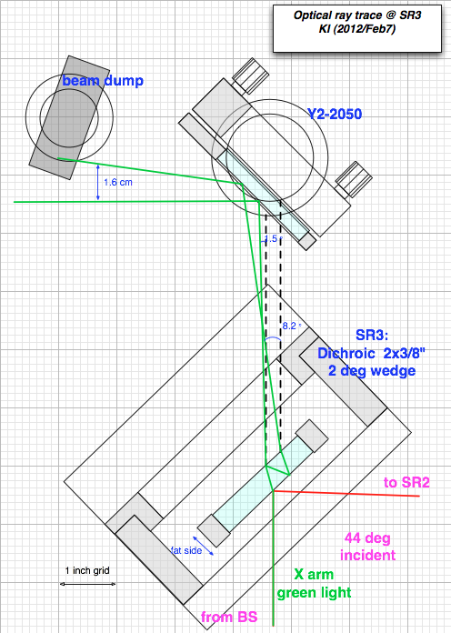
Also for the same reason, we will replace the SR3 mirror too. Unlike the PR3 situation, there looks plenty of space. Therefore we don't have to do some special treatment for this.
- The picture below shows the proposed optical layout around the SR3 region.
- SR3 -- remains at the same position.
- Y2-2050 --- remains at the same position.
- beam dump -- we will newly install one.
►Vacuum Chamber Pictures
ITMY 06/22/2018


ETMY 06/22/2018

