
|
Size: 2009
Comment:
|
Size: 3721
Comment:
|
| Deletions are marked like this. | Additions are marked like this. |
| Line 11: | Line 11: |
| * ''' Gain of whitening filter = 30 dB ''' for both the I and Q. * ''' Demodulation phase = 17.6 deg ''' (at which the I signal doesn't respond to the Michelson displacement). |
* ''' Gain of whitening filter = 30 dB ''' * ''' Demodulation phase = 17.6 deg ''' |
| Line 15: | Line 15: |
| * ''' Gain of whitening filter = 42 dB ''' for both the I and Q. | * ''' Gain of whitening filter = 42 dB ''' |
| Line 26: | Line 26: |
| || REFL11 || ? mW || || REFL33 || ? mW || |
|
| Line 27: | Line 29: |
| || REFL165 || ? mW || | |
| Line 34: | Line 37: |
| ||<-3> ''''' Parameters ''''' || | ||<-3> ''''' MICH sensor parameters ''''' || |
| Line 36: | Line 39: |
| || Estimated Optical gain || 80 uW/m || || | || Estimated Optical gain || uW/m || || |
| Line 38: | Line 41: |
| || Raw optical gain || 5.9052 x10^9 [counts/meter] || = 4 * pi / lambda * (pk value of the error signal)|| | || Raw optical gain || Hm = 1.034768e+11 [counts/m] || = 4 * pi / lambda * (pk value of the error signal)|| || Conversion loss of mixer || 6.5 dB ||from the spec sheet of JMS-1H || || ADC conversion || 1638.4 counts / V || 16 bit, +/-20 V || || Trans impedance at 55 MHz || 556.3 Ohm || [[Electronics/RFPD/AS55| AS55 characterization ]] || || Responsibity of diodes || 0.8 [A/W] || from the spec sheet of CS3102 || || Attenuation in the AS path || || || <<BR>> <<BR>> ||<-3> ''''' PRCL sensor parameters ''''' || || ''' description ''' || ''' values ''' || ''' notes '''|| || Estimated Optical gain || || || || Measured pk-pk Michelson error signal || 1000 counts || Michelson was freely swinging|| || Raw optical gain || Hp = 5.934718e+10 [counts/m] || = 4 * pi / lambda * (pk value of the error signal)|| |
| Line 46: | Line 62: |
| Line 47: | Line 64: |
| * UGF = 55 Hz * Only FM5 (10:1000) was activated. * G = -2 * No limiter in the digital path. * Feeding the signal back to BS. * Dewhitening filters in BS are ON. * Assumption : BS actuator has a pole at 1 Hz with Q = 5 * Time delay = (without considering the effects from the analog circuits and the down sampleing filters.) |
{{attachment:oltf_prmi.png }} |
| Line 56: | Line 66: |
| ||<-4> ''''' MICH servo '''''|| || ''' description '''|| ''' values ''' || ''' notes ''' || || UGF || 100 Hz || || || Filters activated || FM5(10:1000) || || || Gain || G = -5 || || || Feedback || -0.9905 * ITMX + 1 * ITMY || via the output matrix|| || Dewhitening filter || On || in both ITMX and ITMY || || Limiter || off || || || Time delay || 480 usec || without considering the effects from analog circuits and downsampling filters || <<BR>> <<BR>> ||<-4> ''''' PRCL servo '''''|| || ''' description '''|| ''' values ''' || ''' notes ''' || || UGF || 100 Hz || || || Filters activated || FM5(10:1000) || || || Gain || G = - 0.04 || || || Power Normalization || REFL33/POYDC/0.25 || via the normalization matrix || || Feedback || PRM || || || Dewhitening filter || On || PRM || || Limiter || off || || || Time delay || 480 usec || without considering the effects from analog circuits and downsampling filters || <<BR>> . Note: the following values are assumed for fitting the data . {{{ ITMX = 4.913e-09 / f2 [m/counts] ITMY = 4.832e-09 / f2 [m/counts] PRM = 2.022e-08 / f2 [m/counts] }}} . For more details see [[Interferometer_Characterization#Calibration_of_Actuator_responses| summary of the actuators]] |
PRMI Noise budget
Measurements

- 7/Mar/2012 by KI
Sensor in use
- AS55_Q for MIHC
Gain of whitening filter = 30 dB
Demodulation phase = 17.6 deg
- REFL33_I for PRCL
Gain of whitening filter = 42 dB
Demodulation phase = -38.050 deg
LO = 11065910 Hz by a Marconi
DC light
port name
DC power [mW]
AS (before the attenuation)
0.02 mW
AS55
? mW
REFL (before the attenuation)
644 mW
REFL11
? mW
REFL33
? mW
REFL55
? mW
REFL165
? mW
Sidebands
- The values noted here were estimated from the OSAs at the AS and REFL ports.
Optical gains
MICH sensor parameters
description
values
notes
Estimated Optical gain
uW/m
Measured pk-pk Michelson error signal
1000 counts
Michelson was freely swinging
Raw optical gain
Hm = 1.034768e+11 [counts/m]
= 4 * pi / lambda * (pk value of the error signal)
Conversion loss of mixer
6.5 dB
from the spec sheet of JMS-1H
ADC conversion
1638.4 counts / V
16 bit, +/-20 V
Trans impedance at 55 MHz
556.3 Ohm
Responsibity of diodes
0.8 [A/W]
from the spec sheet of CS3102
Attenuation in the AS path
PRCL sensor parameters
description
values
notes
Estimated Optical gain
Measured pk-pk Michelson error signal
1000 counts
Michelson was freely swinging
Raw optical gain
Hp = 5.934718e+10 [counts/m]
= 4 * pi / lambda * (pk value of the error signal)
Conversion loss of mixer
6.5 dB
from the spec sheet of JMS-1H
ADC conversion
1638.4 counts / V
16 bit, +/-20 V
Trans impedance at 55 MHz
556.3 Ohm
Responsibity of diodes
0.8 [A/W]
from the spec sheet of CS3102
Attenuation in the AS path
Servo filters
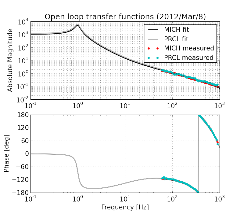
MICH servo
description
values
notes
UGF
100 Hz
Filters activated
FM5(10:1000)
Gain
G = -5
Feedback
-0.9905 * ITMX + 1 * ITMY
via the output matrix
Dewhitening filter
On
in both ITMX and ITMY
Limiter
off
Time delay
480 usec
without considering the effects from analog circuits and downsampling filters
PRCL servo
description
values
notes
UGF
100 Hz
Filters activated
FM5(10:1000)
Gain
G = - 0.04
Power Normalization
REFL33/POYDC/0.25
via the normalization matrix
Feedback
PRM
Dewhitening filter
On
PRM
Limiter
off
Time delay
480 usec
without considering the effects from analog circuits and downsampling filters
- Note: the following values are assumed for fitting the data
     ITMX  = 4.913e-09 / f2   [m/counts]
     ITMY  = 4.832e-09 / f2   [m/counts]
     PRM   = 2.022e-08 / f2  [m/counts]
For more details see summary of the actuators
RAM effects
- Is something going on ?