|
Size: 2568
Comment:
|
Size: 3317
Comment:
|
| Deletions are marked like this. | Additions are marked like this. |
| Line 32: | Line 32: |
| * LO frequency = 11065910 Hz | |
| Line 46: | Line 48: |
| || Estimated Optical gain || 54.1 W/m || || | || Estimated Optical gain || 57.7 W/m || || || Expected optical gain || 47.03 W/m || || |
| Line 49: | Line 52: |
| || mixer gain || 10 || AS55 has a piggy back amplifier || | || demod board gain || 10 || AS55 has a piggy back amplifier || |
| Line 52: | Line 55: |
| || Responsibity of diodes || 0.8 [A/W] || from the spec sheet of CS3102 || || Attenuation in the AS path || || || |
|| Responsibity of diodes || 0.75 [A/W] || from the spec sheet of CS3102 || || Attenuation in the AS path || 0.7 * 0.99 * 0.5 || 0.7 is due to the OMC pick off mirror. The rest are from two BSs in front of the AS55 RFPD || |
| Line 57: | Line 60: |
| . where Pin is the power of the incident beam, ri is the reflectivity of the ITMs, f0 is the frequency of the laser, fm is the modulation frequency, lsch is the Schnupp asymmetry. In order to estimate the expected response, Pin was replaced by the effective power Peff, where all the power attenuation is included such as the transmission of PRM, SRM and the attenuation due to the beam splitters on the AP table. . Peff = Pin * Tp * Ts * Rbs1 * Rbs2 * Romcpickoff, where Pin = 600 mW / Rp. Assuming Rbs1 = 99%, Rbs2 = 50%, Romcpickoff = 70%. |
|
| Line 58: | Line 63: |
| Line 64: | Line 70: |
| * Dewhitening filters in BS are ON. | * Dewhitening filters in BS are OFF. |
Michelson Noise budget

- Some noise curves to be included
- Shot Noise
- Dark (RFPD) Noise
- ADC Noise
- Laser Amplitude noise
- Laser Frequency Noise
- Oscillator Noises
- DAC Noise
- Coil Driver Noise
Measurements
- 6/Mar/2012 by KK and KI
Sensor in use
- AS55_Q
Gain of whitening filter = 30 dB for both the I and Q.
Demodulation phase = 5.4 deg (at which the I signal doesn't respond to the Michelson displacement).
- ~ very tiny DC light is on the RFPD
- Modulation Depths
- Gamma_11 = 0.136
- Gamma_55 = 0.157
- LO frequency = 11065910 Hz
DC light
port name
DC power [mW]
AS55
~0
REFL
1.9 mW
Sidebands
- The values noted here were estimated from the OSAs at the AS and REFL ports.
Optical gains
Parameters
description
values
notes
Estimated Optical gain
57.7 W/m
Expected optical gain
47.03 W/m
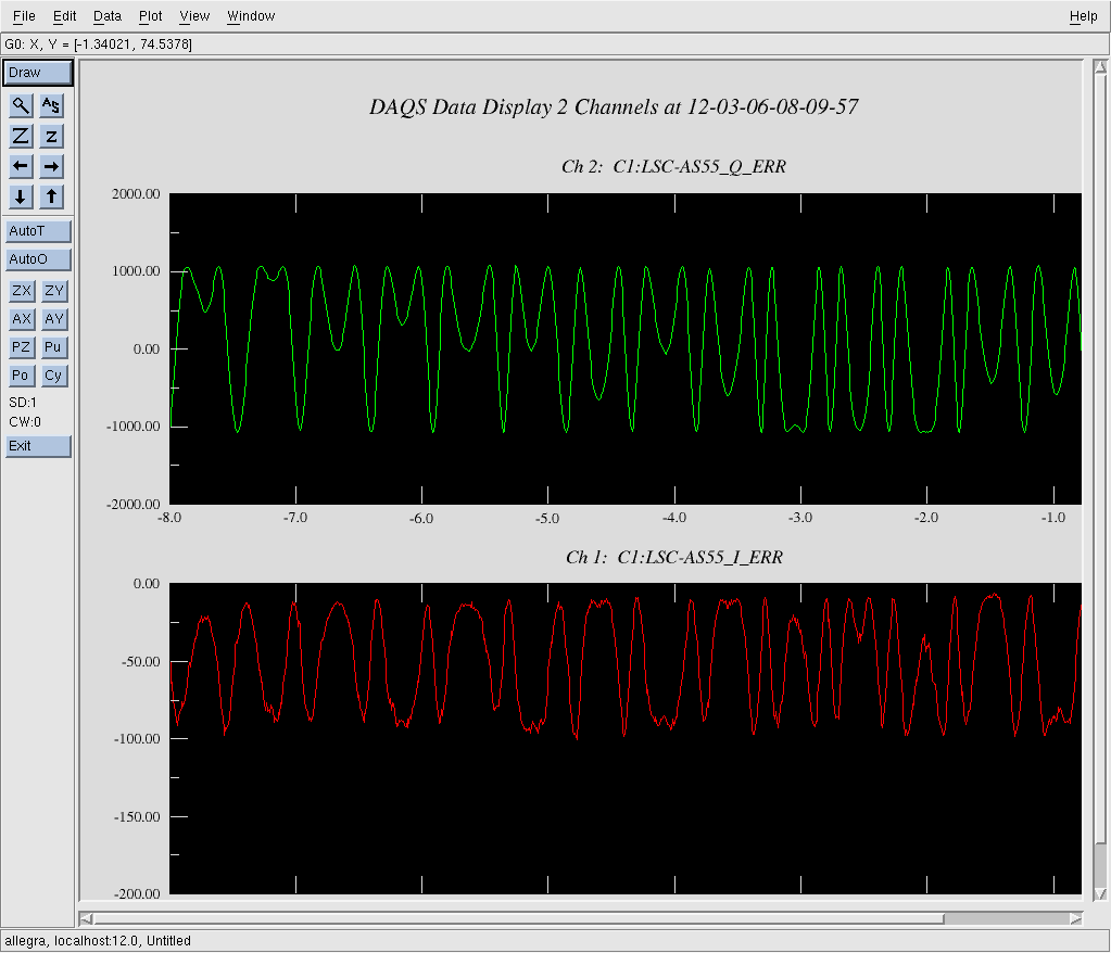
Measured pk-pk Michelson error signal
1000 counts
Michelson was freely swinging
Raw optical gain
5.9052 x10^9 [counts/meter]
= 4 * pi / lambda * (half of pk-pk error signals)
demod board gain
10
AS55 has a piggy back amplifier
ADC conversion
1638.4 counts / V
16 bit, +/-20 V
Trans impedance at 55 MHz
556.3 Ohm
Responsibity of diodes
0.75 [A/W]
from the spec sheet of CS3102
Attenuation in the AS path
0.7 * 0.99 * 0.5
0.7 is due to the OMC pick off mirror. The rest are from two BSs in front of the AS55 RFPD
- Theoretically the MICH error signal can be derived by applying the following equation

- where Pin is the power of the incident beam, ri is the reflectivity of the ITMs, f0 is the frequency of the laser, fm is the modulation frequency, lsch is the Schnupp asymmetry. In order to estimate the expected response, Pin was replaced by the effective power Peff, where all the power attenuation is included such as the transmission of PRM, SRM and the attenuation due to the beam splitters on the AP table.
- Peff = Pin * Tp * Ts * Rbs1 * Rbs2 * Romcpickoff, where Pin = 600 mW / Rp. Assuming Rbs1 = 99%, Rbs2 = 50%, Romcpickoff = 70%.
Servo filters
- UGF = 55 Hz
- Only FM5 (10:1000) was activated.
- G = -2
- No limiter in the digital path.
- Feeding the signal back to BS.
- Dewhitening filters in BS are OFF.
- Assumption : BS actuator has a pole at 1 Hz with Q = 5
- Time delay = (without considering the effects from the analog circuits and the down sampleing filters.)
RAM effects
- There is a big RAM signal in the I signal. The signals float from -100 counts to 0 counts as the Michelson freely swings.
- The amount of the RAM looks changing as a function of time.
- The Q signal looks having not so much RAM effect.
- The highest value seems to be always ~ 0, while the lowest value varies as a function of time. It went to -200 counts some times.