|
Size: 2568
Comment:
|
Size: 2677
Comment:
|
| Deletions are marked like this. | Additions are marked like this. |
| Line 46: | Line 46: |
| || Estimated Optical gain || 56.6 W/m || || | || Estimated Optical gain || 57.7 W/m || || || Expected optical gain || 47.03 W/m || || |
| Line 49: | Line 50: |
| || mixer gain || 10 || AS55 has a piggy back amplifier || | || demod board gain || 10 || AS55 has a piggy back amplifier || |
| Line 52: | Line 53: |
| || Responsibity of diodes || 0.8 [A/W] || from the spec sheet of CS3102 || || Attenuation in the AS path || || || |
|| Responsibity of diodes || 0.75 [A/W] || from the spec sheet of CS3102 || || Attenuation in the AS path || 0.99 * 0.5 || There are two BSs in front of the AS55 RFPD || |
Michelson Noise budget

- Some noise curves to be included
- Shot Noise
- Dark (RFPD) Noise
- ADC Noise
- Laser Amplitude noise
- Laser Frequency Noise
- Oscillator Noises
- DAC Noise
- Coil Driver Noise
Measurements
- 6/Mar/2012 by KK and KI
Sensor in use
- AS55_Q
Gain of whitening filter = 30 dB for both the I and Q.
Demodulation phase = 5.4 deg (at which the I signal doesn't respond to the Michelson displacement).
- ~ very tiny DC light is on the RFPD
- Modulation Depths
- Gamma_11 = 0.136
- Gamma_55 = 0.157
DC light
port name
DC power [mW]
AS55
~0
REFL
1.9 mW
Sidebands
- The values noted here were estimated from the OSAs at the AS and REFL ports.
Optical gains
Parameters
description
values
notes
Estimated Optical gain
57.7 W/m
Expected optical gain
47.03 W/m
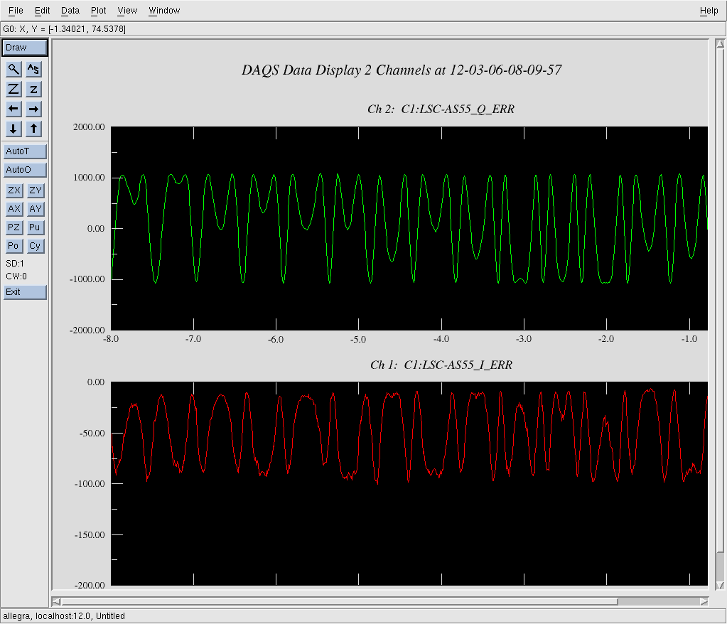
Measured pk-pk Michelson error signal
1000 counts
Michelson was freely swinging
Raw optical gain
5.9052 x10^9 [counts/meter]
= 4 * pi / lambda * (half of pk-pk error signals)
demod board gain
10
AS55 has a piggy back amplifier
ADC conversion
1638.4 counts / V
16 bit, +/-20 V
Trans impedance at 55 MHz
556.3 Ohm
Responsibity of diodes
0.75 [A/W]
from the spec sheet of CS3102
Attenuation in the AS path
0.99 * 0.5
There are two BSs in front of the AS55 RFPD
- Theoretically the MICH error signal can be derived by applying the following equation

Servo filters
- UGF = 55 Hz
- Only FM5 (10:1000) was activated.
- G = -2
- No limiter in the digital path.
- Feeding the signal back to BS.
- Dewhitening filters in BS are ON.
- Assumption : BS actuator has a pole at 1 Hz with Q = 5
- Time delay = (without considering the effects from the analog circuits and the down sampleing filters.)
RAM effects
- There is a big RAM signal in the I signal. The signals float from -100 counts to 0 counts as the Michelson freely swings.
- The amount of the RAM looks changing as a function of time.
- The Q signal looks having not so much RAM effect.
- The highest value seems to be always ~ 0, while the lowest value varies as a function of time. It went to -200 counts some times.