
|
Size: 2042
Comment:
|
← Revision 27 as of 2012-01-03 23:03:06 ⇥
Size: 2646
Comment: converted to 1.6 markup
|
| Deletions are marked like this. | Additions are marked like this. |
| Line 1: | Line 1: |
| = POX = | ## page was renamed from Electronics/POX The data for the following measurements is located at [[https://nodus.ligo.caltech.edu:30889/svn/trunk/docs/upgrade08/RFsystem/RFphotodiodes/POX/|/svn/trunk/docs/upgrade08/RFsystem/RFphotodiodes/POX/]] |
| Line 3: | Line 4: |
| The data for the following measurements is located at [https://nodus.ligo.caltech.edu:30889/svn/trunk/docs/upgrade08/RFsystem/RFphotodiodes/POX/ /svn/trunk/docs/upgrade08/RFsystem/RFphotodiodes/POX/] | [[attachment:POX_modified_schematic.png|Schematic]] |
| Line 7: | Line 8: |
| attachment:transimpedance.png | {{attachment:transimpedance.png}} |
| Line 9: | Line 10: |
| The resonance peaks at 11, 22, and 55 MHz were measured in detail and fit to a resonance curve (see below) with the following results | The above fit was done in LISO in root mode. The results of the fit are the following: |
| Line 11: | Line 12: |
| || Resonance Frequency || Transimpedance at Resonance || Q || || (11.14 +- 0.01) MHz || (2.206 +- 0.001) kOhms || 14.58 +- 0.01 || || (22.68 +- 0.01) MHz || (9.681 +- 0.003) Ohms || 27.66 +- 0.01 || || (55.29 +- 0.01) MHz || (475 +- 2) mOhms || 31.81 +- 0.05 || |
factor = (-2.1 +- 0.2) Ohms delay = (9.57 +- 0.02) ns five poles: || frequency (MHz) || Q || || 11.133 +- 0.003 || 14.3 +- 0.1 || || 11.45 +- 0.06 || 0.595 +- 0.005 || || 25.46 +- 0.02 || 5.89 +- 0.07 || || 224.33 +-0.02 || 124 +- 4 || || 100.7 +- 0.9 || 706.82 +- 0.04 || four zeros: || frequency (MHz) || Q || || 22.67 +- 0.01 || 35 +- 1 || || 55.4 +- 0.3 || (10.0 +- 0.2) x 10^6^ || || 0.93 +- 0.04 || 3.9 +- 0.6 || || 143 +- 3 || 631.94 +- 0.04 || chi^2/ndf = 432 === Alberto's LISO Model === [[attachment:pox_tf.pdf]] |
| Line 18: | Line 39: |
| More detailed transfer functions were measured around the resonance peaks at 11, 22, and 55 MHz. These transfer functions were fit to attachment:resfitfunc.png where ''f'',,0,, is the resonance frequency and ''Gamma'' is the line width. ''Q'' is calculated by ''f'',,0,,/''Gamma''. | More detailed transfer functions were measured around the resonance peaks at 11, 22, and 55 MHz. These transfer functions were fit to {{attachment:resfitfunc.png}} where ''f'',,0,, is the resonant frequency and ''Gamma'' is the line width. ''Q'' is calculated by ''f'',,0,,/''Gamma''. |
| Line 22: | Line 43: |
| attachment:res1.png | {{attachment:res1.png}} |
| Line 36: | Line 57: |
| attachment:res2.png | {{attachment:res2.png}} |
| Line 50: | Line 71: |
| attachment:res3.png | {{attachment:res3.png}} |
| Line 64: | Line 85: |
| attachment:noise.png | {{attachment:noise.png}} |
| Line 66: | Line 87: |
| The noise data was fit to attachment:fitfunc.png with the following results: | The noise data was fit to {{attachment:fitfunc.png}} with the following results: |
| Line 70: | Line 91: |
| ''I'',,d,, = (24.7 +- 0.6) mA | ''I'',,d,, = (247 +- 6) uA |
| Line 74: | Line 95: |
| Note that this value for the transimpedance agrees with the above transfer functions since the noise was measured at 11 MHz instead of the resonance frequency of 11.14 MHz. === Alberto's LISO Model === [[attachment:pox_noise.pdf]] |
|
| Line 76: | Line 103: |
| attachment:timeseries.png | {{attachment:timeseries.png}} |
| Line 78: | Line 105: |
| attachment:dark_spectrum.png | {{attachment:dark_spectrum.png}} |
| Line 82: | Line 109: |
| attachment:POX.jpg | {{attachment:POX.jpg}} |
The data for the following measurements is located at /svn/trunk/docs/upgrade08/RFsystem/RFphotodiodes/POX/

RF Transimpedance

The above fit was done in LISO in root mode. The results of the fit are the following:
factor = (-2.1 +- 0.2) Ohms
delay = (9.57 +- 0.02) ns
five poles:
frequency (MHz) |
Q |
11.133 +- 0.003 |
14.3 +- 0.1 |
11.45 +- 0.06 |
0.595 +- 0.005 |
25.46 +- 0.02 |
5.89 +- 0.07 |
224.33 +-0.02 |
124 +- 4 |
100.7 +- 0.9 |
706.82 +- 0.04 |
four zeros:
frequency (MHz) |
Q |
22.67 +- 0.01 |
35 +- 1 |
55.4 +- 0.3 |
(10.0 +- 0.2) x 106 |
0.93 +- 0.04 |
3.9 +- 0.6 |
143 +- 3 |
631.94 +- 0.04 |
chi^2/ndf = 432
Alberto's LISO Model
Fits To Resonance
More detailed transfer functions were measured around the resonance peaks at 11, 22, and 55 MHz. These transfer functions were fit to  where f0 is the resonant frequency and Gamma is the line width. Q is calculated by f0/Gamma.
11 MHz Resonance
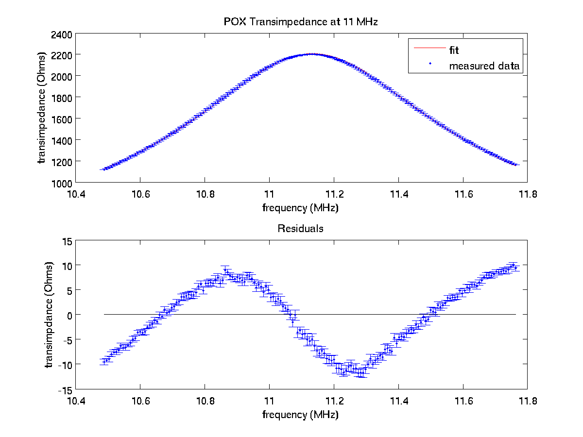
f0 = (11.14 +- 0.01) MHz
Gamma = (764 +- 1) kHz
R0 = (8.38 +- 0.01) x 108 Hz Ohms
C = (11.14 +- 0.05) Ohms
chi^2/ndf = 95.4
22 MHz Resonance
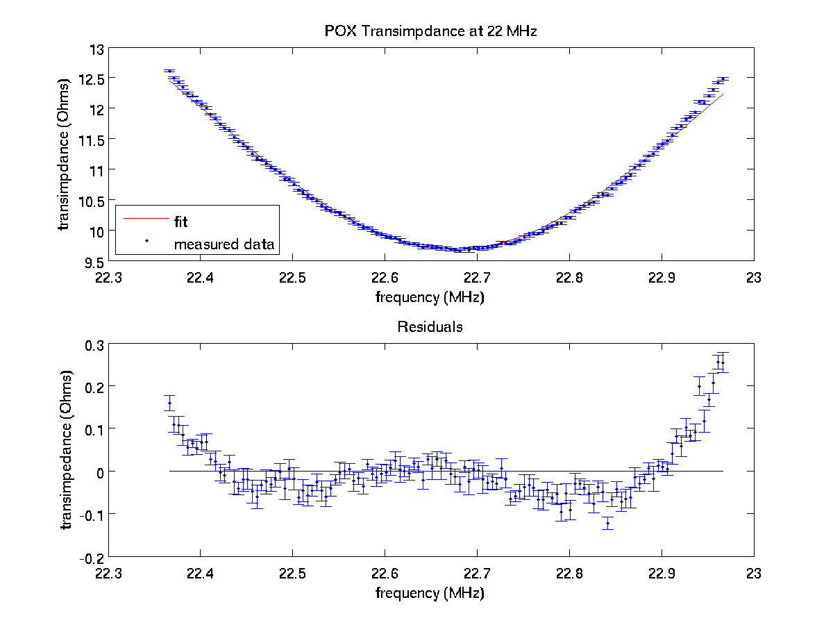
f0 = (22.68 +- 0.01) MHz
Gamma = (820 +- 1) kHz
R0 = (-5.64 +- 0.01) x 106 Hz Ohms
C = (23.44 +- 0.01) Ohms
chi^2/ndf = 12.7
55 MHz Resonance
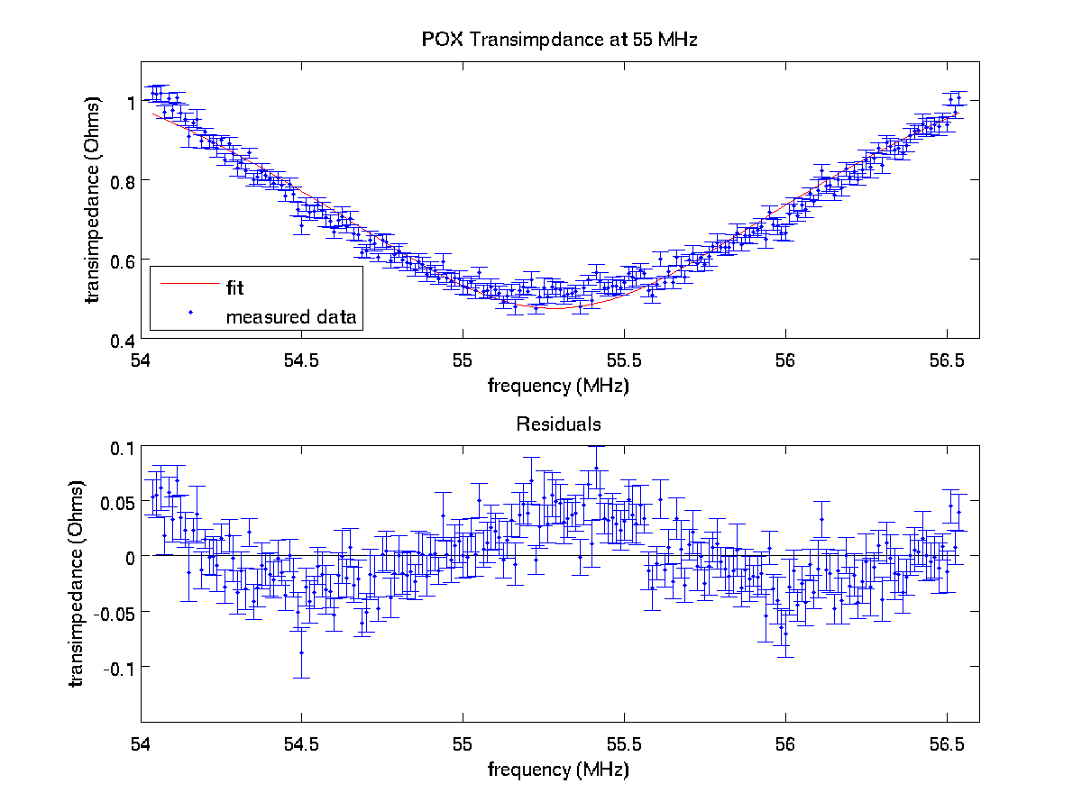
f0 = (55.29 +- 0.01) MHz
Gamma = (1.74 +- 0.01) MHz
R0 = (-9.98 +- 0.01) x 105 Hz Ohms
C = (1.62 +- 0.01) Ohms
chi^2/ndf = 3.22
Noise

The noise data was fit to  with the following results:
ZRF = (2.07 +- 0.01) kOhms
Id = (247 +- 6) uA
chi2 / ndf = 42
Note that this value for the transimpedance agrees with the above transfer functions since the noise was measured at 11 MHz instead of the resonance frequency of 11.14 MHz.
Alberto's LISO Model
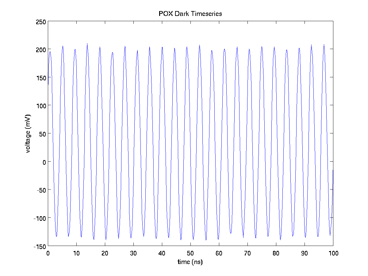
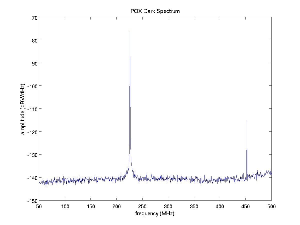
RF Behavior with No Light
Picture of Photodiode
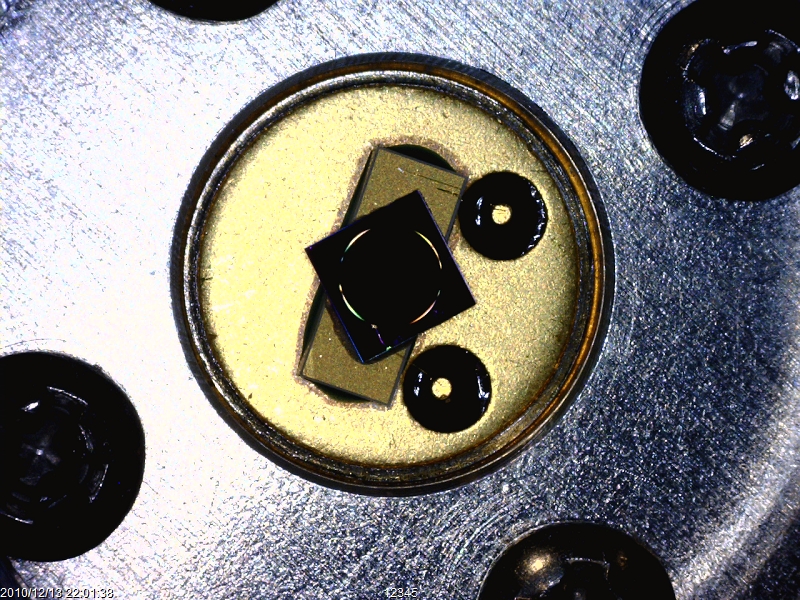
Picture taken on 12/13/2010.