
Contents
Version I (2008) - Prototype
This is the schematic: [attachment:OldBoxSchematic.pdf LIGO D080285]
Some of the labels in this old schematic seem to be wrong. For instance: the RFPD Input label should be Servo Input.
Also, note that since the mixer is an separate part from the circuit board, it does not appear in the schematic.
Evaluation :
2008-11-06 - Today I noticed a strange and unexpected effect on the box. I left it with the input signal plugged in and the output cable disconnected for a couple of days. that was not the first time it happened. Actually I've always done it after leaving the lab to avoid to have a railing signal acting on the laser for hours in case the PLL loses lock. This time though, when I tried to used the box after a couple of days, I found the the output to the piezo had a DC offset of about 3-5 V. Unplugging the input, and also the cable from the mixer to the filter connector connector, didn't cancel the offset and the only thing top do was to unplug the power from the box, wait for a few seconds and then reconnect it. After that, the offset disappeared.
2008-11-07 - What happened yesterday repeated today, even after just few hours of functioning. A RESET button would be nice.
2010-01-18 - The phase shifter does not work. Also, Local Oscillator's signals at frequencies above 80MHz get distorted when passing through the phase-shifter's that is placed before the mixer. Either bypass it or fix it.
Servo Filter
- This is the transfer function of the Servo Filter of the PDH Box as measured between the Servo IN and Servo OUT terminals of the box.
- attachment:Old_PDH_box.png
Version II (2009)
This is the schematic: [attachment:NewBoxSchematic.pdf LIGO D0901351]
- Since the mixer is an separate part from the circuit board, it does not appear in the schematic.
This is how the new version looks like.
[attachment:DSC_1058.JPG Outside]
[attachment:DSC_1063.JPG Inside]
attachment:DSC_1058scaled.JPG
attachment:DSC_1063scaled.JPG
Evaluation (Rana, Dec 16 '09) :
- missing capacitor C25 and C29;
- missing 50 Ohm terminator right after the mixer: it is currently before the Servo Input but it should be just after the mixer;
- voltage dividers missing heat sinks;
- The UPDH boxes can be found inside the RF cabinet in the Y arm of the lab.
Servo Filters Comparison
- The New and the Old PDH box have different servo filters. Here they are compared:

- [attachment:NewandOlfFilterTF.png]
- The way the filter's transfer function has been measured is by a swept sine between the "SERVO INPUT" and the "PIEZO DRIVE OUTPUT" connection on the box front panel. The spectrum analyzer used for the measurement is the SR785 and the source amplitude is set at 0.1V.
Version II-B (2010)
Rana modified the PDH Box v2 to fix the problem of the DC offset.He described what he did in [http://131.215.115.52:8080/AdhikariLab/642 this elog entry]. He also made a LISO model of the circuit that he put in the 40m SVN (ask him where exactly he put it).
Version II - GREEN LOCK 1 (2010)
For use of the end green locking, Kiwamu modified one of PDH boxes newly labeled G1
This is the schematic after the modifications: [attachment:G1_NewBoxSchematic.pdf G1_NewBoxSchematic.pdf] Because the modulation frequency for laser PZTs is relatively low (~200kHz), the mixer was replaced by the low-frequency mixer ZAD-8+[attachment:ZAD-8+.pdf data sheet for ZAD-8+ pdf]
concept of the modifications
- We had to modify the electronics basically for two reasons:
- Change the input impedance of the box
- Change the filter shape
. Because the LPF, which is after the mixer, already has a 50 Ohm input impedance, the PDH box should not have a 50Ohm input impedance. In addition to it, it is better to have 50 Ohm also at another signal input (negative input) of the OP-amp in order to reduce a DC offset.
- Originally the box had two poles and two zeros. It makes the filter shape flat at high frequency.
- We didn't want to have gain at frequency of around 200kHz since phase modulation will be imposed around that frequency. Therefore One more pole at ~20kHz was added in order to reduce the gain at 200kHz.
change from the original circuit
component
name
original value
modified value
comments
resister of positive input for buffer stage
R17
49.9
removed
LPF takes this role as a 50Ohm input impedance
resistor of negative input for buffer stage
R14
1k
49.9
to balance with the input impedance of 50 Ohm
filter capacitor at 1st filter stage
C18
3.3UF
removed
filter capacitor at 1st filter stage
C20
none
0.084UF
to make another pole
filter resistor at 1st filter stage
R28
none
102
to make another pole
feedback resistor at 1st filter stage
R31
10
shorted
to avoid having another zero
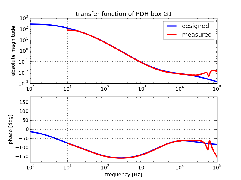
- Here is the transfer function after the modification. The boost was off and the gain knob was 2.0 at this time.
. 
Version II - GREEN LOCK 2 (2011)
- Overview and Concept of the modification
- A servo box for the Y end green PDH locking
- SN17
Details can be found in [http://nodus.ligo.caltech.edu:8080/40m/5937 elog #5937]
- Transfer function fitted by LISO
- pole0:f = 2.3310019441 +- 18.5m (0.794%)
- pole1:f = 1.0258511460 +- 5.56m (0.542%)
- zero0:f = 97.4463217611 +- 4.796 (4.92%)
zero1:f = 10.1737846912k */ 1.676
- factor = 1.5476947197k +- 1.668 (0.108%)
Note that the gain knob was set to 1
- Here is the actual measured transfer function and its fitting
- attachment:SN17_fitting.png