
|
Size: 3693
Comment:
|
← Revision 63 as of 2017-04-20 01:58:36 ⇥
Size: 4570
Comment:
|
| Deletions are marked like this. | Additions are marked like this. |
| Line 5: | Line 5: |
| <<ImageLink(electronics_diagram.png,Upgrade 09/GreenLock/Electronics/electronics_diagram,height=400)>><<TableOfContents(2)>>[[BR]][[BR]] | [[Upgrade 09/GreenLock/Electronics/electronics_diagram|{{attachment:electronics_diagram.png||height=400}}]]<<TableOfContents(2)>><<BR>><<BR>> |
| Line 11: | Line 11: |
| attachment:VCO_range.png | {{attachment:VCO_range.png}} |
| Line 16: | Line 16: |
| attachment:VCO_filter.png | {{attachment:VCO_filter.png}} |
| Line 25: | Line 25: |
| [[BR]] | <<BR>> |
| Line 29: | Line 29: |
| attachment:TF_PDH.png | {{attachment:TF_PDH.png}} == Open loop transfer function == Measured on 22 Dec 2015, with the average level of green transmission at 0.457. {{attachment:Y_PDH_OLTF.pdf||width=700}} |
| Line 34: | Line 39: |
| [[BR]] | <<BR>> |
| Line 39: | Line 44: |
| attachment:SR620.png | {{attachment:SR620.png}} |
| Line 47: | Line 52: |
| [[BR]] | <<BR>> |
| Line 50: | Line 55: |
| <<ImageLink(green_digital.png,Upgrade 09/GreenLock/Electronics/digital_channel ,height=400)>>[[BR]] | [[Upgrade 09/GreenLock/Electronics/digital_channel|{{attachment:green_digital.png||height=400}}]]<<BR>> |
| Line 55: | Line 60: |
| The schematic is available on [https://nodus.ligo.caltech.edu:30889/svn/trunk/alberto/40mUpgrade/RFsystem/RFPDs/GreenLockingBroadBandPD svn] | The schematic is available on [[https://nodus.ligo.caltech.edu:30889/svn/trunk/alberto/40mUpgrade/RFsystem/RFPDs/GreenLockingBroadBandPD|svn]] |
| Line 57: | Line 62: |
| <<ImageLink(Hartmut_RFPD.jpg,height=400)>> | [[attachment:Hartmut_RFPD.jpg|{{attachment:Hartmut_RFPD.jpg||height=400}}]] |
| Line 59: | Line 64: |
| . EG&G SGD-444A Si PIN PD attachment:SGD-444A.pdf | . EG&G SGD-444A Si PIN PD [[attachment:SGD-444A.pdf]] |
| Line 62: | Line 67: |
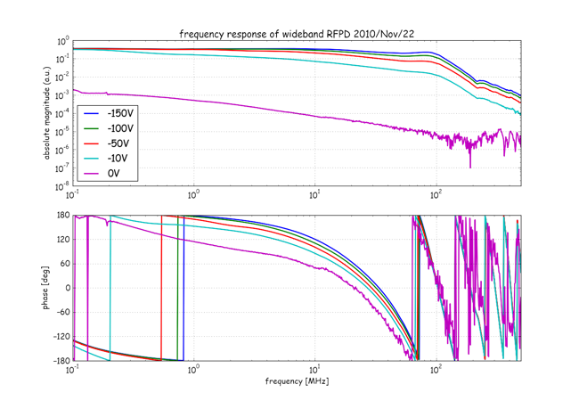
| attachment:RFPD_tf.png | {{attachment:RFPD_tf.png}} |
| Line 65: | Line 70: |
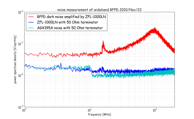
| attachment:RFPDnoise.png | {{attachment:RFPDnoise.png}} |
| Line 67: | Line 72: |
| Here is the noise model for the RFPD using liso. attachment:liso_RFPD.png | Here is the noise model for the RFPD using liso. {{attachment:liso_RFPD.png}} |
| Line 69: | Line 74: |
| [[BR]] | <<BR>> |
| Line 73: | Line 78: |
| . attachment:PDA36A.png | . {{attachment:PDA36A.png}} |
| Line 75: | Line 80: |
| || ''''' parameters ''''' || || trans impedance gain || || [V/A] || || responsibility || || [A/W] || || quantum efficiency || || [%] || |
The PDA36A is an amplified, switchable-gain, silicon detector designed for detection of light signals over 350 – 1100nm wavelength range. || ''''' parameters ''''' || || || || Detector || Si PIN || || || trans impedance gain || 1.5k - 475k (switchable)|| [V/A] || || responsibility || 0.3 || [A/W] at 532 nm || |
| Line 80: | Line 87: |
| || Output Voltage || 0-5 || [V] with 50 Ohm termination || || Band Width || 17 || [MHz] || || Dark noise || || nV/sqrtHz || |
|
| Line 82: | Line 92: |
| [[BR]] | <<BR>> |
| Line 91: | Line 101: |
| [[BR]] | <<BR>> |
| Line 95: | Line 105: |
| attachment:thermalLPF.png | {{attachment:thermalLPF.png}} |
| Line 98: | Line 108: |
| attachment:thermal_actuator.png | {{attachment:thermal_actuator.png}} |
| Line 100: | Line 110: |
| [[BR]] | <<BR>> |
| Line 106: | Line 116: |
| [[BR]] | <<BR>> |
| Line 112: | Line 122: |
| [[BR]] | <<BR>> |
| Line 116: | Line 126: |
| . attachment:tc200.jpg [[BR]] |
. {{attachment:tc200.jpg}} . Manual (USB connector) [[attachment:TC200-Manual.pdf]] . Manual (RS-232 connector) [[attachment:TC200-Manual-RS232.pdf]] <<BR>> |
| Line 123: | Line 134: |
| . attachment:zfl1000.png | . {{attachment:zfl1000.png}} |
| Line 128: | Line 139: |
| . attachment:k18.jpg | . {{attachment:k18.jpg}} |
| Line 132: | Line 143: |
| . attachment:ff888.jpg | . {{attachment:ff888.jpg}} |
| Line 136: | Line 147: |
| . attachment:m22.jpg | . {{attachment:m22.jpg}} |
| Line 138: | Line 149: |
| [[BR]] | <<BR>> |
| Line 148: | Line 159: |
| . attachment:vertex_green_beatbox.pdf . attachment:vertex_green_beatnox.graffle . attachment:freq_divider.pdf . attachment:freq_divider.graffle |
. [[attachment:vertex_green_beatbox.pdf]] . [[attachment:vertex_green_beatnox.graffle]] . [[attachment:freq_divider.pdf]] . [[attachment:freq_divider.graffle]] |
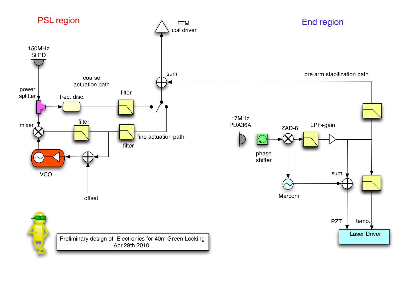
Overview of green electronics
- Preliminary design for the electronics used in 40m green locking.
Contents
- Overview of green electronics
- VCO for frequency tracking
- PDH box
- frequency counter
- digital channel assign
- wideband RFPD for green PLL
- DC PDs
- digital front end filters
- Thermal feedback LPF
- Function Generator
- Summing Amplifier
- Temperature Controller for doubling oves
- RF stuff
- RS232 serial device server
- Vertex BeatBox
VCO for frequency tracking
VCO range
- Synergy VCO part number XXX has 1.2MHz/V VCO range.
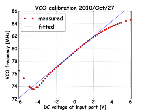
Filter respons
- 80MHz LIGO VCO box is used to readout the frequency of the beat signal precisely.

Noise performance
Capture range and Lock range
- According to a simple calculations...
lock detection and boost
- rms detection
PDH box
Filter Shape
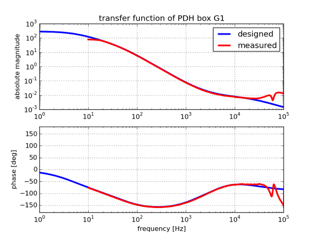
Open loop transfer function
Measured on 22 Dec 2015, with the average level of green transmission at 0.457.
Noise performance
LPF for RF cutoff
Remotely controlled Boost switch
frequency counter
- SR620 is employed to read out the frequency of the beat signal.

setting parameters |
||
readout range |
|
MHz |
DAC bit resolution |
|
|
noise |
|
|
digital channel assign
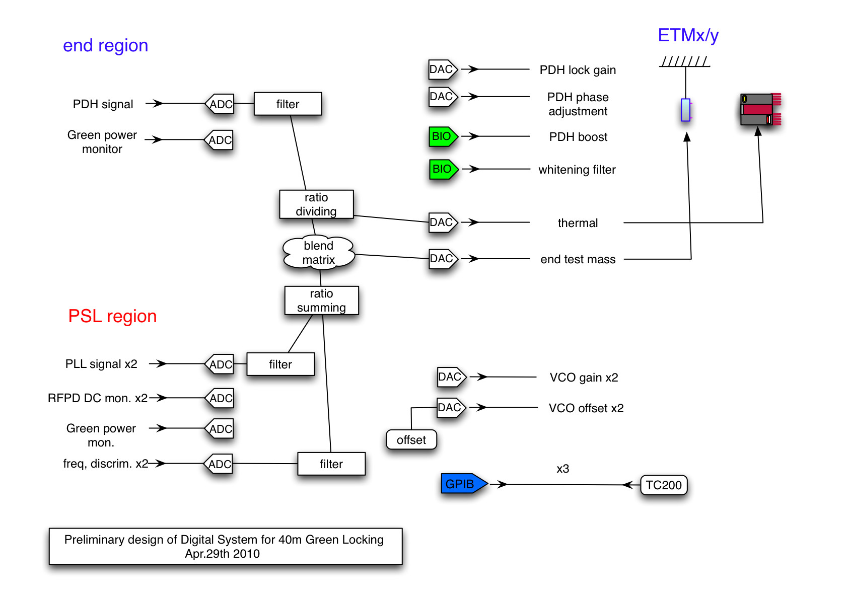
wideband RFPD for green PLL
- A Silicon photodiode with the diameter of 10mm is used. To have a fast response up to about 1MHz -150V is applied onto the photo diode.
The schematic is available on svn

EG&G SGD-444A Si PIN PD SGD-444A.pdf
frequency response
noise performance
Here is the noise model for the RFPD using liso. 
DC PDs
PDA36A
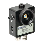
The PDA36A is an amplified, switchable-gain, silicon detector designed for detection of light signals over 350 – 1100nm wavelength range.
parameters |
|
|
Detector |
Si PIN |
|
trans impedance gain |
1.5k - 475k (switchable) |
[V/A] |
responsibility |
0.3 |
[A/W] at 532 nm |
output impedance |
50 |
[Ohm] |
Output Voltage |
0-5 |
[V] with 50 Ohm termination |
Band Width |
17 |
[MHz] |
Dark noise |
|
nV/sqrtHz |
digital front end filters
- anti-aliasing filter
- anti-imaging filter
- whitening filter
Thermal feedback LPF
circuit diagram
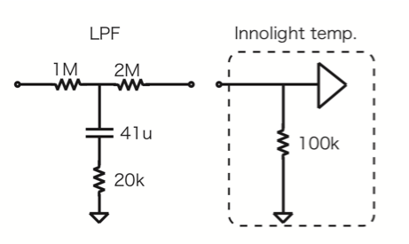
expected transfer function of compound frequency actuator

Function Generator
- To get a phase modulation imposed on the end IR lasers, a function generator is needed.
SR___
Summing Amplifier
In order to send a feedback signal and modulation signal to the laser PZT at the same time, it is desired to have a summing amplifier. The amplifier should handle the signal from DC to 200kHz. Currently this is taken place by SR560.
Diagram
noise performance
Temperature Controller for doubling oves
TC200 from Thorlabs

Manual (USB connector) TC200-Manual.pdf
Manual (RS-232 connector) TC200-Manual-RS232.pdf
RF stuff
low noise amplifier
ZFL-1000 from mini circuit or similar families
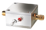
mid power amplifier
power splitter
ZFRSC-42 from mini circuit. DC-4.2GHz

DC block
BLK-89 from mini circuit. 50 Ohm, 100kHz-8GHz

Low frequency mixer
ZAD-8 from mini circuit. 500Hz-10MHz.

RS232 serial device server