
|
Size: 2935
Comment:
|
Size: 3627
Comment:
|
| Deletions are marked like this. | Additions are marked like this. |
| Line 1: | Line 1: |
| ## page was renamed from Upgrade 09/GreenLock/Electronics | |
| Line 2: | Line 3: |
| Line 5: | Line 5: |
| <<ImageLink(electronics_diagram.png,Upgrade 09/GreenLock/Electronics/electronics_diagram,height=400)>> <<TableOfContents(2)>> [[BR]] [[BR]] |
<<ImageLink(electronics_diagram.png,Upgrade 09/GreenLock/Electronics/electronics_diagram,height=400)>><<TableOfContents(2)>>[[BR]][[BR]] |
| Line 16: | Line 10: |
| Line 17: | Line 12: |
| Line 25: | Line 19: |
| == Capture range and Lock range == . According to a simple calculations... |
|
| Line 29: | Line 25: |
| [[BR]] | |
| Line 32: | Line 27: |
| [[BR]] | |
| Line 38: | Line 32: |
| Line 40: | Line 33: |
| Line 43: | Line 34: |
| Line 47: | Line 37: |
.SR620 is employed to read out the frequency of the beat signal. |
. SR620 is employed to read out the frequency of the beat signal. |
| Line 52: | Line 41: |
| ||<-3> '''''setting parameters''''' || | || '''''setting parameters''''' || |
| Line 61: | Line 50: |
<<ImageLink(green_digital.png,Upgrade 09/GreenLock/Electronics/digital_channel ,height=400)>> [[BR]] |
<<ImageLink(green_digital.png,Upgrade 09/GreenLock/Electronics/digital_channel ,height=400)>>[[BR]] |
| Line 69: | Line 54: |
| Line 70: | Line 56: |
<<ImageLink(Hartmut_RFPD.jpg,height=400)>> . EG&G SGD-444A Si PIN PD attachment:SGD-444A.pdf |
|
| Line 77: | Line 67: |
| Here is the noise model for the RFPD using liso. attachment:liso_RFPD.png |
Here is the noise model for the RFPD using liso. attachment:liso_RFPD.png |
| Line 84: | Line 73: |
| attachment:PDA36A.png | . attachment:PDA36A.png |
| Line 86: | Line 75: |
| ||<-4> ''''' parameters ''''' || | || ''''' parameters ''''' || |
| Line 88: | Line 77: |
| || responsibility || || [A/W]|| || quantum efficiency || || [%]|| |
|| responsibility || || [A/W] || || quantum efficiency || || [%] || || output impedance || 50 || [Ohm] || |
| Line 93: | Line 84: |
| = digital front end filters= | = digital front end filters = . anti-aliasing filter |
| Line 95: | Line 87: |
| . anti-aliasing filter |
|
| Line 107: | Line 97: |
| == expected transfer function of composed frequency actuator == | == expected transfer function of compound frequency actuator == |
| Line 109: | Line 99: |
| Line 113: | Line 103: |
| To get a phase modulation imposed on the end IR lasers, a function generator is needed. | . To get a phase modulation imposed on the end IR lasers, a function generator is needed. |
| Line 115: | Line 106: |
| Line 119: | Line 108: |
| In order to send a feedback signal and modulation signal to the laser PZT at the same time, it is desired to have a summing amplifier. The amplifier should handle the signal from DC to 200kHz. Currently this is taken place by SR560. |
In order to send a feedback signal and modulation signal to the laser PZT at the same time, it is desired to have a summing amplifier. The amplifier should handle the signal from DC to 200kHz. Currently this is taken place by SR560. |
| Line 125: | Line 111: |
| Line 127: | Line 112: |
| Line 131: | Line 115: |
| . TC200 from Thorlabs | . ''' TC200 ''' from Thorlabs . attachment:tc200.jpg |
| Line 137: | Line 122: |
| . ''' ZFL-1000 ''' from mini circuit or similar families . attachment:zfl1000.png |
|
| Line 139: | Line 127: |
| . ''' ZFRSC-42 ''' from mini circuit. DC-4.2GHz . attachment:k18.jpg |
|
| Line 140: | Line 131: |
| . ''' BLK-89''' from mini circuit. 50 Ohm, 100kHz-8GHz . attachment:ff888.jpg |
|
| Line 141: | Line 135: |
| . ZAD-8 from mini circuit | . ''' ZAD-8''' from mini circuit. 500Hz-10MHz. . attachment:m22.jpg |
| Line 148: | Line 143: |
| [[BR]] ----- = RS232 serial device server = . here are the candidates . ''' 5100A ''' from Moxa. . ''' SeaLink ''' from SeaLevel |
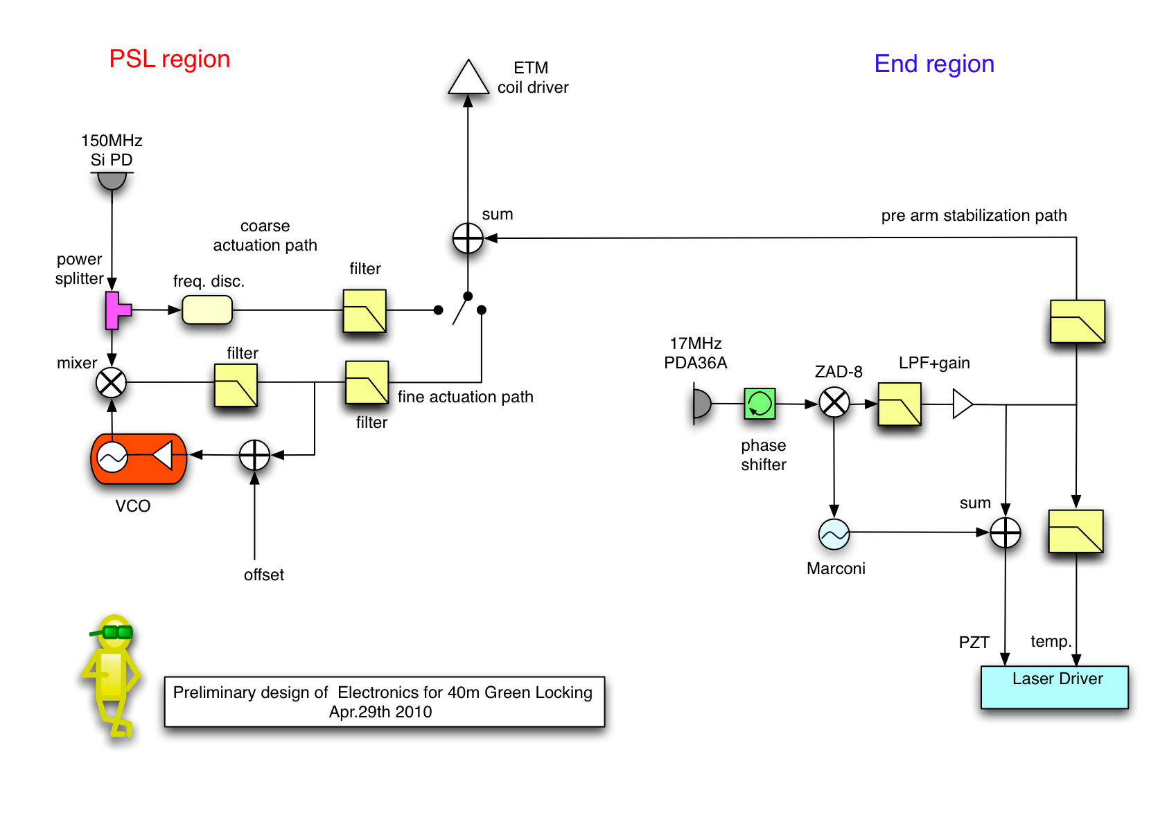
Overview of green electronics
- Preliminary design for the electronics used in 40m green locking.
Contents
- Overview of green electronics
- VCO for frequency tracking
- PDH box
- frequency counter
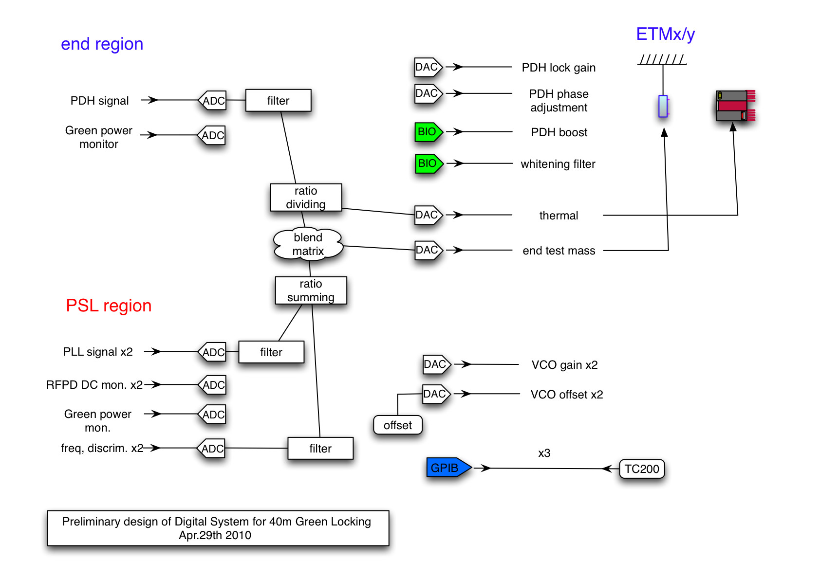
- digital channel assign
- wideband RFPD for green PLL
- DC PDs
- digital front end filters
- Thermal feedback LPF
- Function Generator
- Summing Amplifier
- Temperature Controller for doubling oves
- RF stuff
- Power Supply and Cables
- RS232 serial device server
VCO for frequency tracking
VCO range
- Synergy VCO part number XXX has 1.2MHz/V VCO range.
attachment:VCO_range.png
Filter respons
- 80MHz LIGO VCO box is used to readout the frequency of the beat signal precisely.
attachment:VCO_filter.png
Noise performance
Capture range and Lock range
- According to a simple calculations...
lock detection and boost
- rms detection
PDH box
Filter Shape
attachment:TF_PDH.png
Noise performance
LPF for RF cutoff
Remotely controlled Boost switch
frequency counter
- SR620 is employed to read out the frequency of the beat signal.
attachment:SR620.png
setting parameters |
||
readout range |
|
MHz |
DAC bit resolution |
|
|
noise |
|
|
digital channel assign
wideband RFPD for green PLL
- A Silicon photodiode with the diameter of 10mm is used. To have a fast response up to about 1MHz -150V is applied onto the photo diode.
The schematic is available on [https://nodus.ligo.caltech.edu:30889/svn/trunk/alberto/40mUpgrade/RFsystem/RFPDs/GreenLockingBroadBandPD svn]
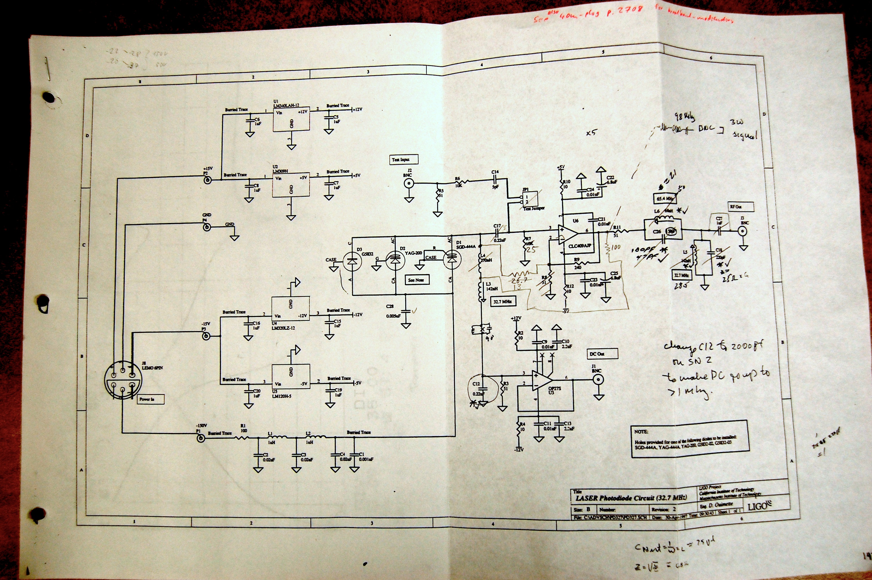
EG&G SGD-444A Si PIN PD attachment:SGD-444A.pdf
frequency response
attachment:RFPD_tf.png
noise performance
attachment:RFPDnoise.png
Here is the noise model for the RFPD using liso. attachment:liso_RFPD.png
DC PDs
PDA36A
- attachment:PDA36A.png
parameters |
||
trans impedance gain |
|
[V/A] |
responsibility |
|
[A/W] |
quantum efficiency |
|
[%] |
output impedance |
50 |
[Ohm] |
digital front end filters
- anti-aliasing filter
- anti-imaging filter
- whitening filter
Thermal feedback LPF
circuit diagram
attachment:thermalLPF.png
expected transfer function of compound frequency actuator
attachment:thermal_actuator.png
Function Generator
- To get a phase modulation imposed on the end IR lasers, a function generator is needed.
SR___
Summing Amplifier
In order to send a feedback signal and modulation signal to the laser PZT at the same time, it is desired to have a summing amplifier. The amplifier should handle the signal from DC to 200kHz. Currently this is taken place by SR560.
Diagram
noise performance
Temperature Controller for doubling oves
TC200 from Thorlabs
- attachment:tc200.jpg
RF stuff
low noise amplifier
ZFL-1000 from mini circuit or similar families
- attachment:zfl1000.png
mid power amplifier
power splitter
ZFRSC-42 from mini circuit. DC-4.2GHz
- attachment:k18.jpg
DC block
BLK-89 from mini circuit. 50 Ohm, 100kHz-8GHz
- attachment:ff888.jpg
Low frequency mixer
ZAD-8 from mini circuit. 500Hz-10MHz.
- attachment:m22.jpg
Power Supply and Cables
HV cables (-150V) for photodiode bias
15V and 24V lines