
|
Size: 1563
Comment:
|
Size: 2446
Comment:
|
| Deletions are marked like this. | Additions are marked like this. |
| Line 1: | Line 1: |
| = Electronics = == outline == |
= outline = |
| Line 9: | Line 7: |
| <<TableOfContents(2)>> |
|
| Line 12: | Line 13: |
| == VCO == | = VCO for frequency tracking = == VCO range == . Synergy VCO part number XXX has 1.2MHz/V VCO range. attachment:VCO_range.png == Filter respons == |
| Line 15: | Line 22: |
| attachment:VCO_filter.png == Noise performance == == lock detection and boost == . rms detection |
|
| Line 18: | Line 33: |
| == PDH box == | = PDH box = == Filter Shape == |
| Line 20: | Line 36: |
| . what kind of modification | == Noise performance == == LPF for RF cutoff == == Low frequency mixer == == Remotely controlled Boost switch == |
| Line 24: | Line 46: |
| == frequency counter == | = frequency counter = |
| Line 38: | Line 60: |
| == digital channel assign == | = digital channel assign = |
| Line 45: | Line 67: |
| == whitening filter == . what is the specification for each channel [[BR]] ----- == wideband RFPD for green PLL == |
= wideband RFPD for green PLL = |
| Line 55: | Line 71: |
| === frequency response === | == frequency response == |
| Line 58: | Line 74: |
| === noise performance === | == noise performance == |
| Line 66: | Line 82: |
| == digital front end == | = DC PDs = == PDA36A == attachment:PDA36A.png ||<-4> ''''' parameters ''''' || || trans impedance gain || || [V/A] || || responsibility || || [A/W]|| || quantum efficiency || || [%]|| [[BR]] ----- = digital front end filters= |
| Line 72: | Line 99: |
| . whitening filter |
|
| Line 74: | Line 103: |
| == Power Supply and Cables == === HV cables (-150V) for photodiode bias === === 15V and 24V lines === |
= Thermal feedback LPF = == circuit diagram == attachment:thermalLPF.png == expected transfer function of composed frequency actuator == attachment:thermal_actuator.png [[BR]] ----- = Function Generator = To get a phase modulation imposed on the end IR lasers, a function generator is needed. === SR___ === [[BR]] ----- = Temperature Controller for doubling oves = . TC200 from Thorlabs [[BR]] ----- = Power Supply and Cables = == HV cables (-150V) for photodiode bias == == 15V and 24V lines == |
outline
- Preliminary design for the electronics used in 40m green locking.
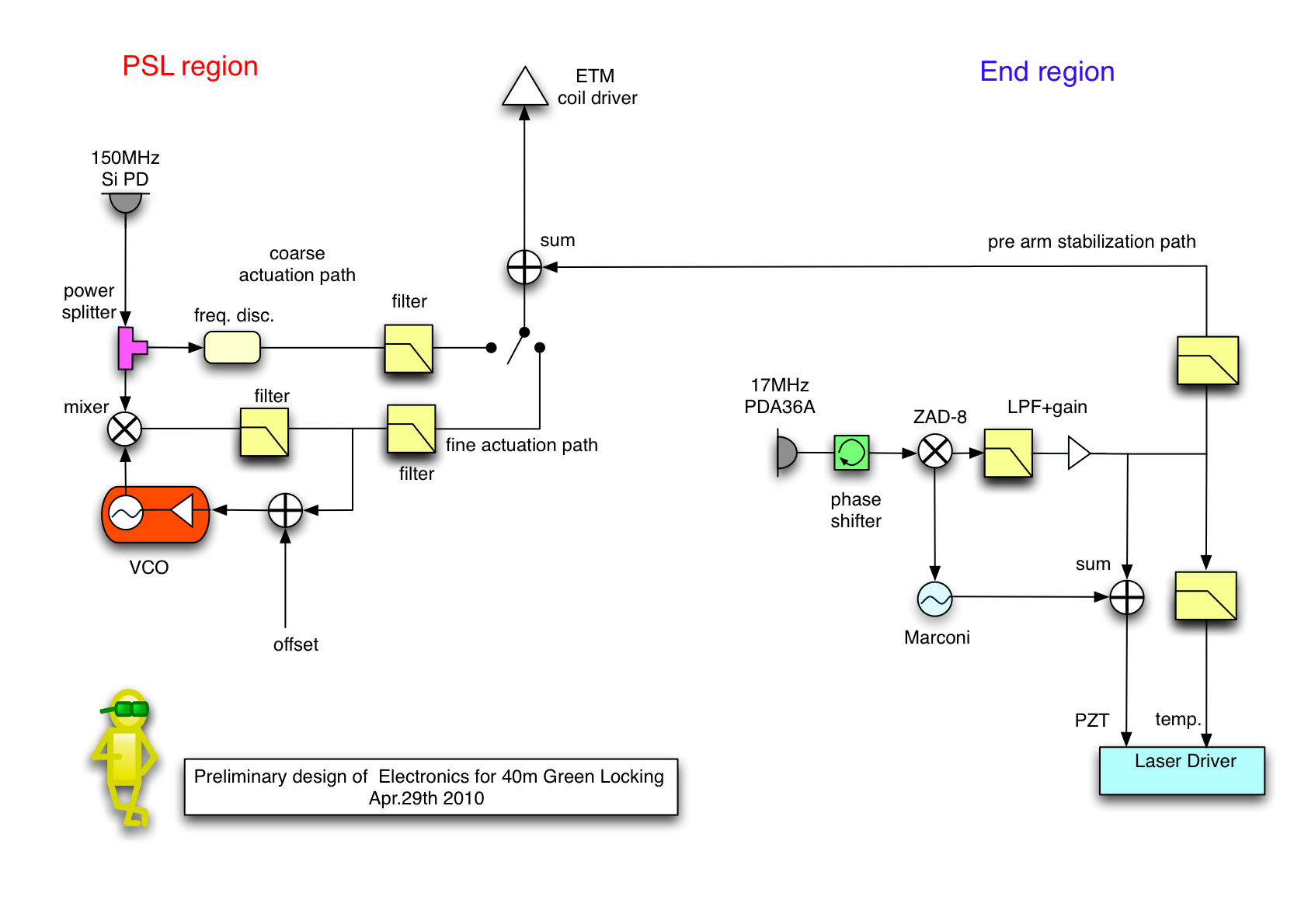
Contents
VCO for frequency tracking
VCO range
- Synergy VCO part number XXX has 1.2MHz/V VCO range.
attachment:VCO_range.png
Filter respons
- 80MHz LIGO VCO box is used to readout the frequency of the beat signal precisely.
attachment:VCO_filter.png
Noise performance
lock detection and boost
- rms detection
PDH box
Filter Shape
Noise performance
LPF for RF cutoff
Low frequency mixer
Remotely controlled Boost switch
frequency counter
- SR620 is employed to read out the frequency of the beat signal.
attachment:SR620.png
setting parameters |
||
readout range |
|
MHz |
DAC bit resolution |
|
|
noise |
|
|
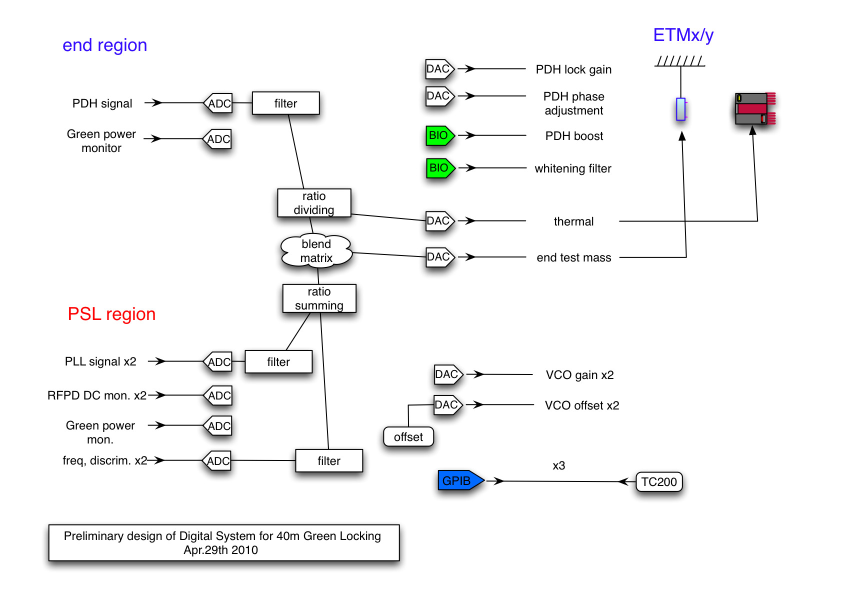
digital channel assign
wideband RFPD for green PLL
- A Silicon photodiode with the diameter of 10mm is used. To have a fast response up to about 1MHz -150V is applied onto the photo diode.
The schematic is available on [https://nodus.ligo.caltech.edu:30889/svn/trunk/alberto/40mUpgrade/RFsystem/RFPDs/GreenLockingBroadBandPD svn]
frequency response
attachment:RFPD_tf.png
noise performance
attachment:RFPDnoise.png
Here is the noise model for the RFPD using liso. attachment:liso_RFPD.png
DC PDs
PDA36A
- attachment:PDA36A.png
parameters |
|||
trans impedance gain |
|
[V/A] |
|
responsibility |
|
[A/W] |
|
quantum efficiency |
|
[%] |
|
= digital front end filters=
- anti-aliasing filter
- anti-imaging filter
- whitening filter
Thermal feedback LPF
circuit diagram
attachment:thermalLPF.png
expected transfer function of composed frequency actuator
attachment:thermal_actuator.png
Function Generator
- To get a phase modulation imposed on the end IR lasers, a function generator is needed.
SR___
Temperature Controller for doubling oves
. TC200 from Thorlabs
Power Supply and Cables
HV cables (-150V) for photodiode bias