
|
Size: 4038
Comment:
|
Size: 3821
Comment:
|
| Deletions are marked like this. | Additions are marked like this. |
| Line 1: | Line 1: |
| = FREQUENCY OFFSET LOCKING = | = Frequency Offset Locking (FOL) for Dual Wavelength Laser Stabilisation = |
| Line 3: | Line 3: |
| '''Overview''' | == Overview == |
| Line 5: | Line 5: |
| In order for Absolute Length Measurement to be effective, the differential frequency (beat frequency) between prestabilized laser (PSL) and Auxiliary Laser (AUX) must remain constant. | In order for the Arm Length Stabilization (ALS) system to be effective in its purpose, the beat frequency between the AUX lasers and the PSL must be within the efficient working range of ALS (< 50 MHz). Thus, our purpose in Frequency Offset Locking (FOL) is to design a feedback-control loop that will keep this beat frequency well within the working range of ALS, so that manual tuning of auxiliary (AUX) laser frequencies may be avoided. |
| Line 7: | Line 7: |
| However, over time, the AUX frequency tends to wander due to things like temperature change. Thus, we employ our frequency offset locking (FOL) system. | Frequency offset locking works by sampling light from each laser source, PSL and AUX laser, and combining them to produce a beat note which corresponds to the difference between the frequencies of either laser. |
| Line 9: | Line 9: |
| Frequency offset locking works by sampling light from each laser source, PSL and AUX, and combining them, in-line, to produce a beat note. The value of which corresponds to the difference between the frequencies of either laser. | The combined PSL and AUX light is sensed at an RF photodiode and an RF frequency counter is used to measure the beat frequency. A digital PID control loop compares the detected beat frequency with the desired beat frequency to produce an error signal. The error signal is then converted back to an analog signal, to actuate on the temperature of the crystal in the AUX laser to keep its frequency within the desired range. |
| Line 11: | Line 11: |
| This light is then fed into a photodiode, the signal from which is digitized, and sent into a digital PID control loop. The PID Controller uses this signal as the current state of the system, which is further analyzed to produce an error signal. | == Schematic == A schematic of the setup for FOL is shown below: |
| Line 13: | Line 14: |
| The error is then converted back to an analog signal, which actuates upon the frequency of the AUX laser, keeping it within the desired range. | {{attachment:FOLschematic.png||height=600}} |
| Line 15: | Line 16: |
| The actuator is a temperature control, which controls the dimensions of the crystal resonator within the NPRO via thermal expansion. | ---- |
| Line 17: | Line 18: |
| Through this scheme, we hope to effectively achieve a constant frequency offset between the AUX and PSL. | == Project Tasks == ||'''Tasks'''||Who||Status||Last updated|| ||||||''General tasks''|| ||Make procurements list and purchase stuff||MT||Done||Oct 9|| ||Find an appropriate C-lens for telescope||EG|| || || ||Find out the fiber mode|| || || ||||||''End laser fiber setup''|| ||Designate space for the setup at end tables|| || || ||Design telescopes for coupling light into the fiber|| || || ||Layout the fiber along 40m arms in insulated tubes|| || || ||||||''PSL fiber setup''|| ||Designate space on PSL table|| || || ||Find the fiber beam splitter(FBS) mode|| || || ||Design a telescope to couple light into the FBS mode|| || || ||||||''Beat note setup''|| ||Couple fiber to fiber|| || || ||Combine PSL and end laser with appropriate polarization (50/50 --> 90/10)|| || || ||Detecting beatnote at the PD|| || || ||||||''Frequency counter setup''|| ||Hook up frequency counter|| || || ||Read beat frequency on StripTool|| || || ||||||''End laser thermal actuator characterization''|| ||||||''Digital servo''|| ||||||''MISC tasks''|| ||Behavior of PM fiber to temperature fluctuations|| || || ||Polarization controller characterization|| || || |
| Line 19: | Line 45: |
| <<TableOfContents(4)>> <<BR>> <<BR>> <<BR>> -------- |
== Procurements list == ||''Component''||''Quantity needed/procured''||''Part number''||''Order status''||''As of''|| ||70m PM fiber||4/4||Corning PM98-U25A||Procured||Oct 7|| ||6 axis fiber mount||6/4||Thorlabs K6XS||?||Oct 7|| ||Fiber mounting adapters||6/4||Thorlabs SM1FCA||Need to rder more||Oct 7|| ||Fiber collimators ||6/3||Thorlabs CFC-2X-C||Need to order||Oct 7|| ||Fiber collimator mounts||6/2||Thorlabs AD9.5F||Need to order||Oct 7|| ||HR1064 mirrors||?/plenty||CVI Y1 mirrors||Procured||Oct 7|| ||Lenses for telescopes||?/1064nm lens kit available||?||?||Oct 7|| ||Fiber insulating tubes||2/2||-||Procured||Oct 7|| ||Fiber BS for splitting PSL light between the arms(PM = PM+PM in 50-50)||1/1||Afw Tech POBC-64--C-(s)PM-7-2-25 dB|| Procured||Oct 7|| ||PM fiber mating sleeves (FC/APC)||?/0||?||?||Oct 7|| ||Fiber BC for beat note between arm and PSL (PM+PM=SM)||2/2||Afw tech POBC-64-C-1-7-2-25 dB||Procured|| Oct 7|| ||Polarization controller||?/1||Acrobat PCM4102-333|| Procured|| Oct 7|| ||Fiber BS for splitting combined light between PD and pick off (SM 10-90)||2/2||Afw Tech FOSC-1-64-10-C-(s)3m-H64-2||Procured||Oct 7|| ||Fiber coupled PD||2/1||Thorlabs FPD310||Procured||Oct7|| ||Frequency counter||2/2||Minicircuits UFC6000||Procured||Oct 7|| |
| Line 25: | Line 63: |
| == Optics == | == Other links == |
| Line 27: | Line 65: |
| === Purpose === To implement a system that will efficiently and effectively sample and beat light from both PSL and AUX, to act as an input to the digital PID loop, which will actuate temperature servos in the AUX lasers. === Methods === ==== Razor Blade Measurement ==== Razor Blade, or knife edge beam profiling, is a technique which allows manual measurement of a gaussian beam's properties (read: beam waist). A razor blade, or other reliably straight edge, is translated across a beam which is then incident upon a photodiode or power meter. As the blade is translated, corresponding measurements of blade location and power supplied to photodiode are taken. The measurements should then be repeated in the direction orthogonal to both optical axis, and original direction or translation, to give a two dimensional measurement of spot size. This measurement is repeated many times along the optical axis, preferably somewhere near the beam waist. If this is impossible, a lens may be used to create a new waist (w_f), from which the original beam waist may be calculated using ABCD matrices. The blade position vs beam power data is then fit to V(x) = (.5*Vmax)*(1-erf((sqrt(2)*(x-x0))/wz))+c . x0 and c are offsets in x and V, correspondingly, with the independent variable being x. The other fit parameters being Vmax (maximum power available to photodiode), and wz, the spot size at the current value of z. The spot size data is then fit to w(z) = w_o*sqrt(1 + ((z-b)lambda) / (pi*w_o^2))^2), where z is the independent variable (blade position along optical axis), b corresponds to an offset from zero in the x, lambda the laser wavelength, and w_o the beam waist. b and w_o are fit parameters that should be returned, lambda should be known (1064nm in our case). This technique returns beam waist and location, relative to some point along z chosen to be zero. ==== Beam Profiler ==== Measurement using a beam profiler essentially replaces the razor blade setup, and takes measurements of spot size far more efficiently. The profilers is translated along the optical axis, where values of wz and z should be taken, again preferably near the beam waist. These data are then fit in the same way as in the razor blade measurement (see above) to yield a beam waist and location. === Measurements === ==== Razor Blade ==== The razor blade measurement proved difficult, and ended up requiring six trials. Details of the final round of measurement are included here: ''Setup'' {{attachment:RazorBladeSchematic.png|alt txt|width=500 height = 200}} ''Data'' [[/RazorBladeData | Razor Blade Data]] ==== Beam Profiler ==== == Electronics == |
[[\Frequency Counter Characterization]] |
Frequency Offset Locking (FOL) for Dual Wavelength Laser Stabilisation
Overview
In order for the Arm Length Stabilization (ALS) system to be effective in its purpose, the beat frequency between the AUX lasers and the PSL must be within the efficient working range of ALS (< 50 MHz). Thus, our purpose in Frequency Offset Locking (FOL) is to design a feedback-control loop that will keep this beat frequency well within the working range of ALS, so that manual tuning of auxiliary (AUX) laser frequencies may be avoided.
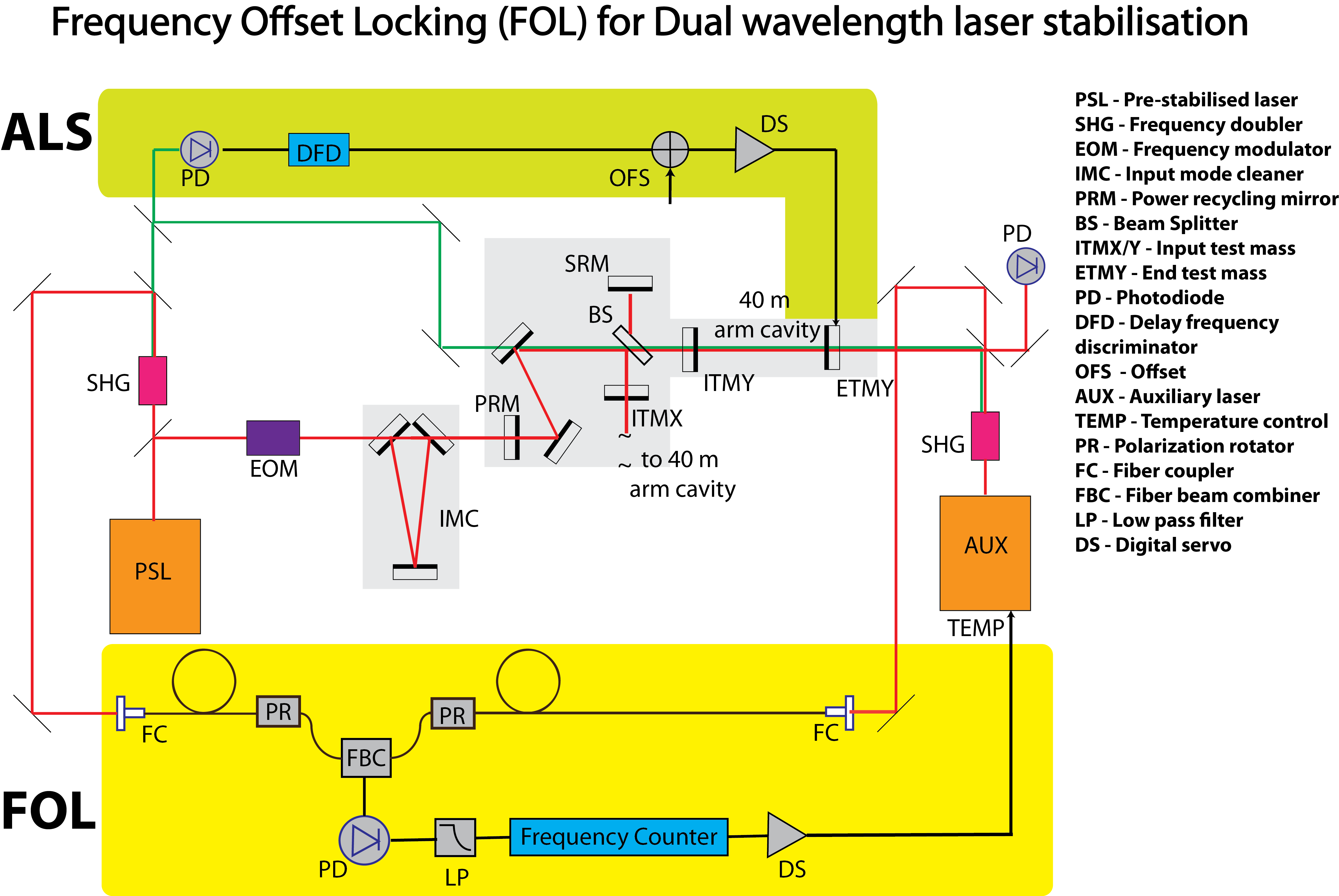
Frequency offset locking works by sampling light from each laser source, PSL and AUX laser, and combining them to produce a beat note which corresponds to the difference between the frequencies of either laser.
The combined PSL and AUX light is sensed at an RF photodiode and an RF frequency counter is used to measure the beat frequency. A digital PID control loop compares the detected beat frequency with the desired beat frequency to produce an error signal. The error signal is then converted back to an analog signal, to actuate on the temperature of the crystal in the AUX laser to keep its frequency within the desired range.
Schematic
A schematic of the setup for FOL is shown below:
Project Tasks
Tasks |
Who |
Status |
Last updated |
General tasks |
|||
Make procurements list and purchase stuff |
MT |
Done |
Oct 9 |
Find an appropriate C-lens for telescope |
EG |
|
|
Find out the fiber mode |
|
|
|
End laser fiber setup |
|||
Designate space for the setup at end tables |
|
|
|
Design telescopes for coupling light into the fiber |
|
|
|
Layout the fiber along 40m arms in insulated tubes |
|
|
|
PSL fiber setup |
|||
Designate space on PSL table |
|
|
|
Find the fiber beam splitter(FBS) mode |
|
|
|
Design a telescope to couple light into the FBS mode |
|
|
|
Beat note setup |
|||
Couple fiber to fiber |
|
|
|
Combine PSL and end laser with appropriate polarization (50/50 --> 90/10) |
|
|
|
Detecting beatnote at the PD |
|
|
|
Frequency counter setup |
|||
Hook up frequency counter |
|
|
|
Read beat frequency on StripTool |
|
|
|
End laser thermal actuator characterization |
|||
Digital servo |
|||
MISC tasks |
|||
Behavior of PM fiber to temperature fluctuations |
|
|
|
Polarization controller characterization |
|
|
|
Procurements list
Component |
Quantity needed/procured |
Part number |
Order status |
As of |
70m PM fiber |
4/4 |
Corning PM98-U25A |
Procured |
Oct 7 |
6 axis fiber mount |
6/4 |
Thorlabs K6XS |
? |
Oct 7 |
Fiber mounting adapters |
6/4 |
Thorlabs SM1FCA |
Need to rder more |
Oct 7 |
Fiber collimators |
6/3 |
Thorlabs CFC-2X-C |
Need to order |
Oct 7 |
Fiber collimator mounts |
6/2 |
Thorlabs AD9.5F |
Need to order |
Oct 7 |
HR1064 mirrors |
?/plenty |
CVI Y1 mirrors |
Procured |
Oct 7 |
Lenses for telescopes |
?/1064nm lens kit available |
? |
? |
Oct 7 |
Fiber insulating tubes |
2/2 |
- |
Procured |
Oct 7 |
Fiber BS for splitting PSL light between the arms(PM = PM+PM in 50-50) |
1/1 |
Afw Tech POBC-64--C-(s)PM-7-2-25 dB |
Procured |
Oct 7 |
PM fiber mating sleeves (FC/APC) |
?/0 |
? |
? |
Oct 7 |
Fiber BC for beat note between arm and PSL (PM+PM=SM) |
2/2 |
Afw tech POBC-64-C-1-7-2-25 dB |
Procured |
Oct 7 |
Polarization controller |
?/1 |
Acrobat PCM4102-333 |
Procured |
Oct 7 |
Fiber BS for splitting combined light between PD and pick off (SM 10-90) |
2/2 |
Afw Tech FOSC-1-64-10-C-(s)3m-H64-2 |
Procured |
Oct 7 |
Fiber coupled PD |
2/1 |
Thorlabs FPD310 |
Procured |
Oct7 |
Frequency counter |
2/2 |
Minicircuits UFC6000 |
Procured |
Oct 7 |