
|
Size: 1673
Comment:
|
Size: 2194
Comment:
|
| Deletions are marked like this. | Additions are marked like this. |
| Line 1: | Line 1: |
| = FREQUENCY OFFSET LOCKING = | = Frequency Offset Locking (FOL) for Dual Wavelength Laser Stabilisation = |
| Line 3: | Line 3: |
| '''Overview''' | == Overview == |
| Line 5: | Line 5: |
| In order for the Arm Length Stabilization (ALS) system to be effective in its purpose, the beat frequency between transmitted AUX and PSL must be within the working range of ALS. That is to say, up to 150 MHz. Thus, our purpose in Frequency Offset Locking (FOL) is to design a feedback-control circuit that will keep this beat frequency well within the working range of ALS, so that manual tuning of auxiliary (AUX) laser frequencies may be avoided. | In order for the Arm Length Stabilization (ALS) system to be effective in its purpose, the beat frequency between the AUX lasers and the PSL must be within the efficient working range of ALS (< 50 MHz). Thus, our purpose in Frequency Offset Locking (FOL) is to design a feedback-control loop that will keep this beat frequency well within the working range of ALS, so that manual tuning of auxiliary (AUX) laser frequencies may be avoided. |
| Line 7: | Line 7: |
| AUX frequency tends to wander due to things like temperature change. Frequency offset locking works by sampling light from each laser source, PSL and AUX, and combining them in-line, to produce a beat note. The value of which corresponds to the difference between the frequencies of either laser. | Frequency offset locking works by sampling light from each laser source, PSL and AUX laser, and combining them to produce a beat note which corresponds to the difference between the frequencies of either laser. |
| Line 9: | Line 9: |
| This light is then fed into a photodiode, the signal from which is digitized, and sent into a digital PID control loop. The PID Controller uses this signal as the current state of the system, which is further analyzed to produce an error signal. | The combined PSL and AUX light is sensed at an RF photodiode and an RF frequency counter is used to measure the beat frequency. A digital PID control loop compares the detected beat frequency with the desired beat frequency to produce an error signal. The error signal is then converted back to an analog signal, to actuate on the temperature of the crystal in the AUX laser to keep its frequency within the desired range. |
| Line 11: | Line 11: |
| The error is then converted back to an analog signal, which actuates upon the frequency of the AUX laser, keeping it within the desired range. The actuator is a temperature control, which controls the dimensions of the crystal resonator within the NPRO via thermal expansion. | == Schematic == A schematic of the setup for FOL is shown below: |
| Line 13: | Line 14: |
| Through this scheme, we hope to effectively achieve a controlled frequency offset between the AUX and PSL. | {{attachment:FOLschematic.png||height=600}} |
| Line 15: | Line 16: |
| === Optics -- Project Plan === | == Tasks == |
| Line 17: | Line 18: |
| {{attachment:projectPlan.png}} | === Step 1 === '''Laying out the fiber from end tables''' *Find out the fiber mode *Designate space for the setup at end tables *Design telescopes for coupling light into the fiber *Layout the fiber along 40m arms in insulated tubes |
| Line 19: | Line 25: |
| [[\Fiber characterization]] | '''Shopping list''' ||''Component''||''Quantity needed/procured''||''Part number''||''Order status''||''As of''|| ||70m PM fiber||4/3||?||Procured||Oct 7|| ||6 axis fiber mount||6/?||?||?||Oct 7|| ||Fiber couplers||6/?||?||?||Oct 7|| ||HR1064 mirrors||?/plenty||CVI Y1 mirror||Procured||Oct7|| ||Lenses for telescope||?/1064nm lens kit available||?||?||Oct7|| ||Fiber insulating tubes||2/2||?||Procured||Oct7|| |
| Line 21: | Line 34: |
| [[\Fiber coupling]] | === Step 2 === '''PSL setup''' *Divide the PSL beam *Find the fiber beam splitter mode *DEsign a telescope to couple light into the fiber BS mode |
| Line 23: | Line 40: |
| [[\Beat Note Setup]] | == Other links == |
| Line 25: | Line 42: |
| === Electronics and Controller Design -- Project Plan === {{attachment:Plan.png}} |
[[\Frequency Counter Characterization]] |
Frequency Offset Locking (FOL) for Dual Wavelength Laser Stabilisation
Overview
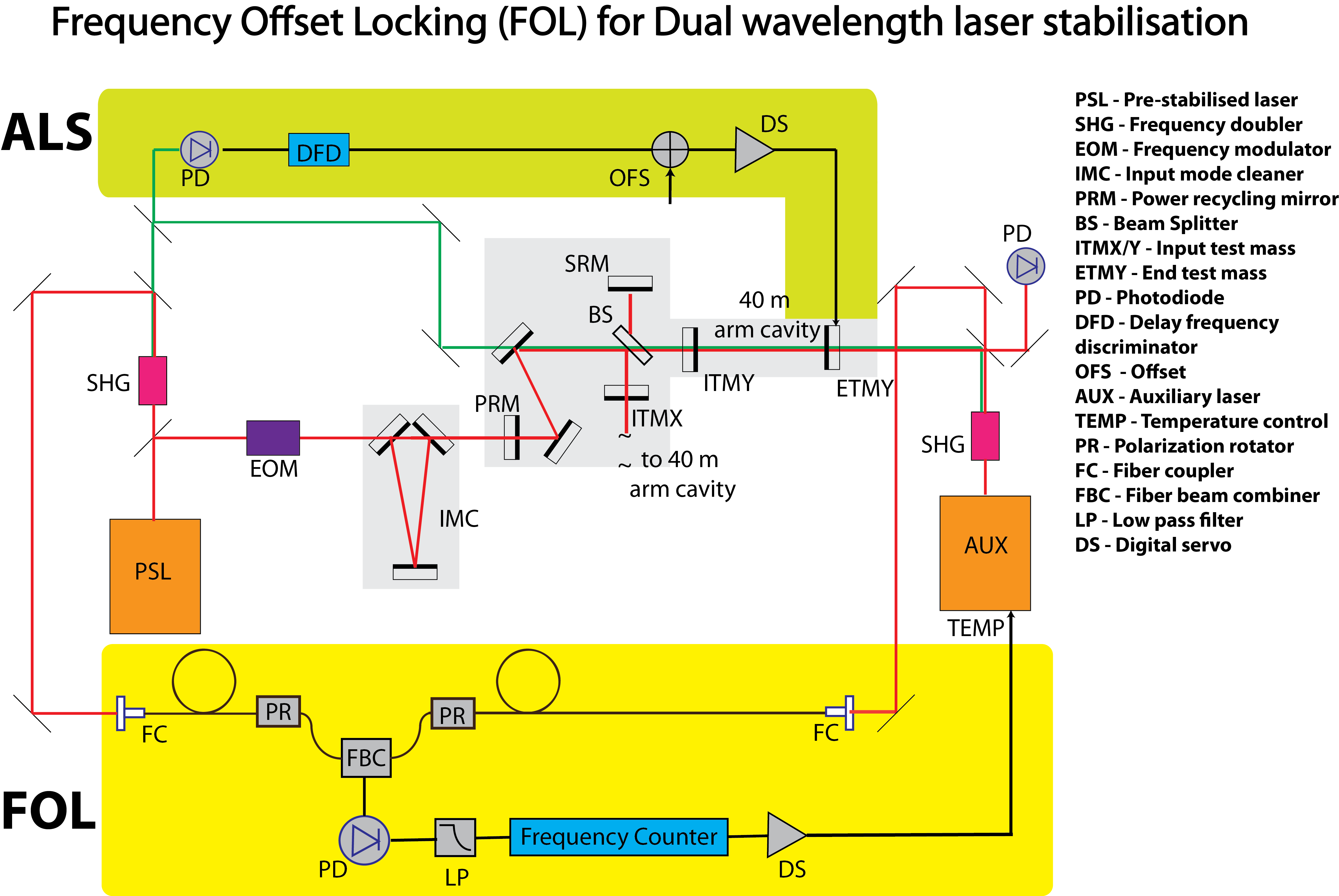
In order for the Arm Length Stabilization (ALS) system to be effective in its purpose, the beat frequency between the AUX lasers and the PSL must be within the efficient working range of ALS (< 50 MHz). Thus, our purpose in Frequency Offset Locking (FOL) is to design a feedback-control loop that will keep this beat frequency well within the working range of ALS, so that manual tuning of auxiliary (AUX) laser frequencies may be avoided.
Frequency offset locking works by sampling light from each laser source, PSL and AUX laser, and combining them to produce a beat note which corresponds to the difference between the frequencies of either laser.
The combined PSL and AUX light is sensed at an RF photodiode and an RF frequency counter is used to measure the beat frequency. A digital PID control loop compares the detected beat frequency with the desired beat frequency to produce an error signal. The error signal is then converted back to an analog signal, to actuate on the temperature of the crystal in the AUX laser to keep its frequency within the desired range.
Schematic
A schematic of the setup for FOL is shown below:
Tasks
Step 1
Laying out the fiber from end tables
- Find out the fiber mode
- Designate space for the setup at end tables
- Design telescopes for coupling light into the fiber
- Layout the fiber along 40m arms in insulated tubes
Shopping list
Component |
Quantity needed/procured |
Part number |
Order status |
As of |
70m PM fiber |
4/3 |
? |
Procured |
Oct 7 |
6 axis fiber mount |
6/? |
? |
? |
Oct 7 |
Fiber couplers |
6/? |
? |
? |
Oct 7 |
HR1064 mirrors |
?/plenty |
CVI Y1 mirror |
Procured |
Oct7 |
Lenses for telescope |
?/1064nm lens kit available |
? |
? |
Oct7 |
Fiber insulating tubes |
2/2 |
? |
Procured |
Oct7 |
Step 2
PSL setup
- Divide the PSL beam
- Find the fiber beam splitter mode
- DEsign a telescope to couple light into the fiber BS mode