
|
Size: 2439
Comment:
|
Size: 2279
Comment:
|
| Deletions are marked like this. | Additions are marked like this. |
| Line 13: | Line 13: |
| {{attachment:CTD.jpg|alt text|width=600 height=200}} | {{attachment:CTD.png|alt text|width=600 height=200}} |
| Line 25: | Line 25: |
| We can conclude that the amplitude of the beatnote as a function of the end-laser frequency (or the local oscillator frequency) will give the information about the cavity resonance frequencies and hence the effect of the mirror distortions can be mapped. | we can conclude that '''the amplitude of the beatnote as a function of the end-green laser frequency (or the local oscillator frequency) will hold the information about the cavity resonance frequencies and hence the effect of the mirror distortions created by various heat patterns can be mapped'''. |
| Line 27: | Line 27: |
| === Simulation/Modelling === | |
| Line 28: | Line 29: |
| ==== SIS ==== | |
| Line 29: | Line 31: |
| 1. | |
| Line 30: | Line 33: |
| == Fact-finding == | ==== Design and construction ==== |
| Line 32: | Line 35: |
| 1. What are the ideal cavity parameters? (a reference to compare the different heating models) | 1. Heater array |
| Line 34: | Line 37: |
| 2. Desired tuneable range and achievable range | 2. Heater electronics |
| Line 36: | Line 39: |
| 3. Heaters and heating patterns | 3. Telescope components |
| Line 38: | Line 41: |
| 4. Practical/hardware limitations in implementing | 4. Apertures 5. PLL for green laser 6. Inversion matrix 7. Front ends 8. |
| Line 40: | Line 51: |
== Simulation/Modelling == 1. Find the ideal/real cavity parameters (higher order mode degeneracy) - SIS 2. Frequency tuning - SIS 3. Heating patterns - COMSOL 4. Thermally perturbed cavity analysis - SIS |
==== Tasks/Timeline ==== |
Tuning Fabry-Perot cavity modal frequencies using controlled thermoelastic deformations on mirror surface
Goal
To correct for the modal frequency shifts in the FP arm cavity that arise from the spatial inhomogeneities on the mirror surface. This will be done by imaging heat patterns on the ETM surface. The thermoelastic deformations created on the mirror surface introduces phase shifts to the cavity modes. The green ALS system will be used to mode scan the cavity continuously. A feedback control system will actively correct for the frequency shifts based on the cavity mode scan information.
The lessons learned from this exercise will help in designing/implementing a similar kind of system for the folding mirrors in the signal recycling cavity.
System Overview
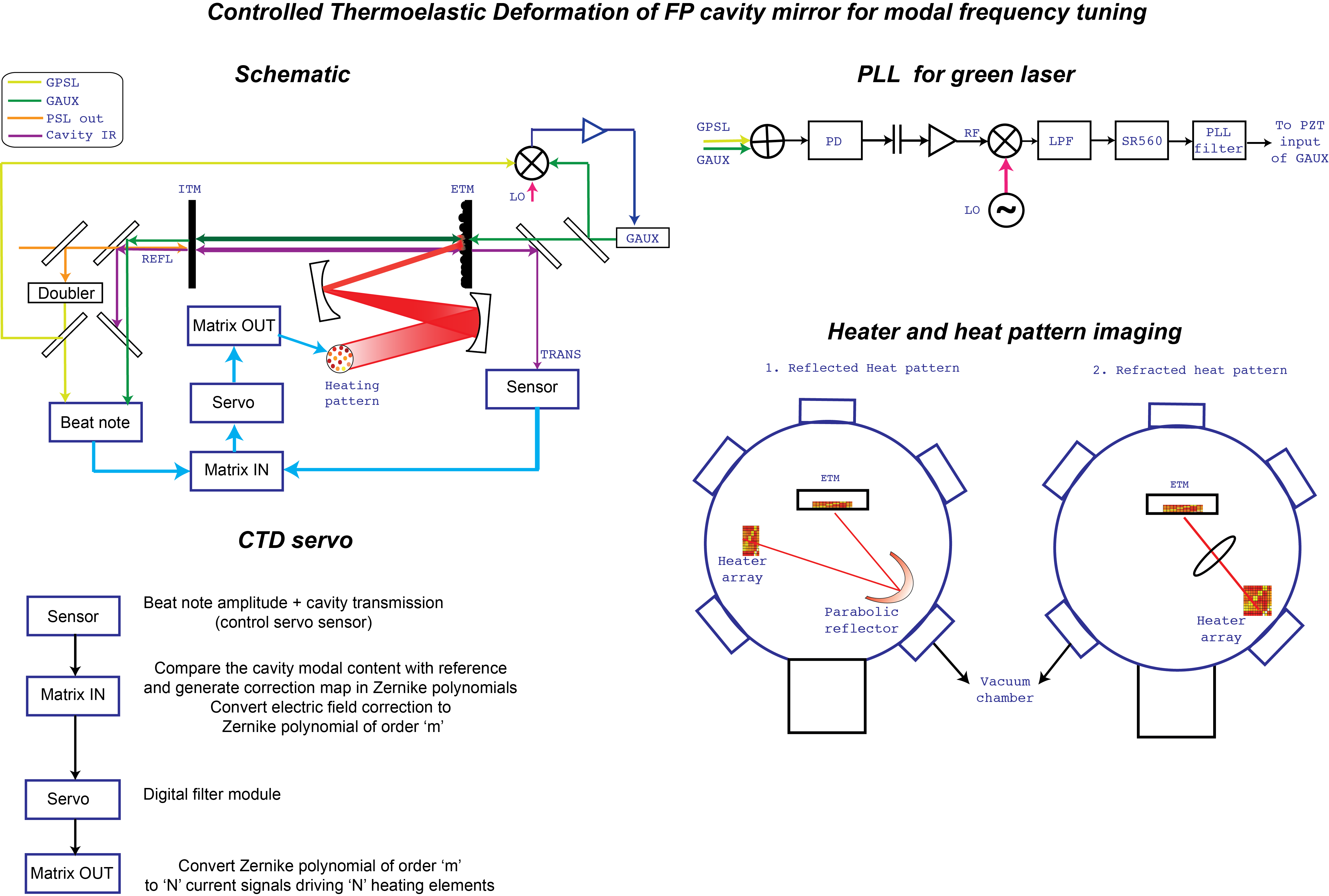
Description
The PSL laser is locked to the arm cavity using the PDH error signal. The green laser is injected from the ETM side of the arm. The relative phase between the two lasers is kept constant using a phase-locked-loop (PLL) servo. The transmitted end-green from the arm interferes with the frequency-doubled PSL and produces a beatnote.
Taking into account the following:
- The amplitude of the beatnote depends on the intensity of the transmitted green.
- Changing the frequency of the end-green laser (using the PLL local oscillator) will affect it's resonance conditions in the arm cavity and excite the various transverse modes.
- The frequencies at which the various transverse mode resonances occur depend on the spatial inhomogeneities on the mirror surface.
we can conclude that the amplitude of the beatnote as a function of the end-green laser frequency (or the local oscillator frequency) will hold the information about the cavity resonance frequencies and hence the effect of the mirror distortions created by various heat patterns can be mapped.
Simulation/Modelling
SIS
Design and construction
- Heater array
- Heater electronics
- Telescope components
- Apertures
- PLL for green laser
- Inversion matrix
- Front ends