
|
Size: 8344
Comment:
|
Size: 8074
Comment:
|
| Deletions are marked like this. | Additions are marked like this. |
| Line 123: | Line 123: |
| 4. | '''Hardware check/prep''' 1. Calibrate the heater 2. Bake in-vacuum components 3. Check components if they are ready to go in-vacuum |
| Line 126: | Line 132: |
| --> | '''In-vacuum installation''' |
| Line 128: | Line 134: |
| * Hardware: Prepare list of hardware needed (Beat PDs, optics, cables, feedthroughs...). [''estimating a week time''] Design and order custom parts (heater and heater electronics, in-vacuum mounts, telescope,...). [''estimating a couple of weeks for design and unknown time between ordering and receiving the parts'']. |
1. Install heater and telescope components |
| Line 132: | Line 136: |
| * Installation: ''Affects regular 40m activities.'' | 2. Check heater operation |
| Line 134: | Line 138: |
| (1) Out-of vacuum work : PLL setup, Electronics (heater tests and ), Front ends (arrange for the , (2) In-vacuum work : Install heater and heat imaging parts. [''estimating a month''] |
'''Front-ends''' |
| Line 138: | Line 140: |
| * Servo design: Compute transfer function matrices. |
1. Connect the analog world with the digital world |
| Line 141: | Line 142: |
| ==== Effects of CTD work on the 40m ==== | '''Building the CTD model''' |
| Line 143: | Line 144: |
| * Installing the PLL for the green laser will affect the ALS system considerably. * In-vacuum work. |
1. SIMULINK model the CTD syatem '''Getting things to work''' 1. Connect the various parts of the system 2. Optimize the servo 3. Testing and troubleshooting |
Tuning Fabry-Perot cavity modal frequencies using controlled thermoelastic deformations on mirror surface
Goal
To correct for the modal frequency shifts in the FP arm cavity. We are not looking to change the overall RoC of the mirror or suppress the higher order modes; but creating phase shifts that would result in desired modal frequency shifts. This will be done by imaging heat patterns on the ETM surface. The thermoelastic deformations created on the mirror surface introduces phase shifts to the cavity modes. The green ALS system will be used to mode scan the cavity continuously. A feedback control system will actively correct for the frequency shifts based on the cavity mode scan information obtained from the green probe laser mode scans.
The lessons learned from this exercise will help in designing/implementing a similar kind of system for the folding mirrors in the signal recycling cavity, so that we can control the fine details of mode healing/harming.
Overview
Description
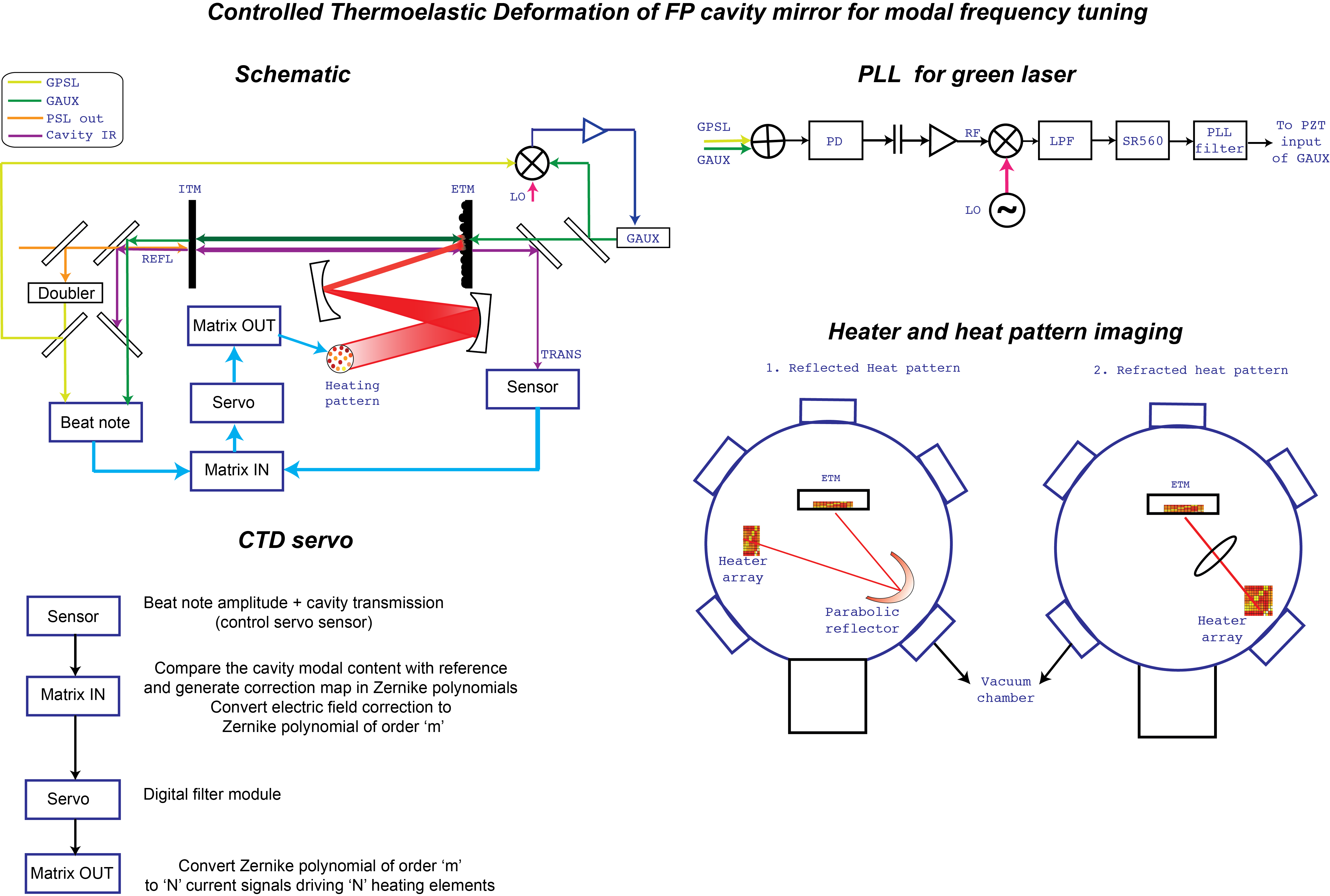
The PSL laser is locked to the arm cavity using the IR PDH error signal. The green laser is injected from the ETM side of the arm. The relative phase between the two lasers is kept constant using a phase-locked-loop (PLL) servo. The transmitted end-green from the arm interferes with the frequency-doubled PSL and produces a beatnote.
Taking into account the following:
- The amplitude of the beatnote depends on the intensity of the transmitted green.
- Changing the frequency of the end-green laser (using the PLL local oscillator) will affect the resonance conditions in the arm cavity and excite the various transverse modes.
- The frequencies at which the various transverse mode resonances occur depend on the spatial inhomogeneities on the mirror surface.
we can conclude that the amplitude of the beatnote as a function of the end-green laser frequency (or the local oscillator frequency) will hold the information about the cavity resonance frequencies and hence the effect of the mirror distortions created by various heat patterns can be mapped.
We expect to correct for frequency shifts in the order of a few KHz. This corresponds to deformations/length change of the order of a few nm.
Simulation/Modeling
COMSOL model: COMSOL related work are updated in the 40m svn
Model thermal deformations on the ETM. Use the generated correction maps and estimate actuation area, deformation depths and points on the ETM. Based on this, we can decide the limitations on the system if we consider only positive corrections (thermo-elastic expansion) or if it is essential to design a heating system that can generate positive and negative corrections to the mirror.
- SIS/Finesse modeling of the arm cavity using the phase map measurements made for the ITM and ETM.
This will give an estimate of the modal content of the arm cavity which we will use as reference to start with. The cavity field can be expressed in terms of Zernike polynomials of order 'm'. Comparing this with desired cavity field, we can obtain the correction in terms of Zernike polynomials. This should give an idea about the range of frequency shifts we are looking at for each higher order mode that has to be brought about by the thermal deformation system, the highest mode order correction we are going to limit ourselves to.
- Other simulations: Estimate the heating power that can bring about these deformations on the HR surface of the mirror. Check for limitations posed on the number of heating elements (heat pixels in the heater array) and their size. Scattering losses associated with controlled frequency shifts. Time constants involved with the servo. Noise estimates.
Design and construction
Heater array: Customised heater array. Array size, individual heating element size and pixelation of heater will be decided based on the required heating power, desired actuation area on the ETM, space limitations in the vacuum chamber...
Heater electronics: Control over heat power generated by individual heat elements is mandatory. The current driver heating the elements of the array will be the actuator driven by the CTD feedback servo.
Telescope components: Based on the pros and cons, we must decide if
--> we will reflect or refract heat patterns on the ETM. Layout as to how each of these will look like, is shown in the figure.
--> the heater will be installed in-vacuum or out-of vacuum (For out-of-vacuum heater installation, we will have to think about compatible vacuum windows).
--> the heater and the reflecting/refracting elements will be installed on fixed or movable stages. Telescope specs will be decided based on actuation area and the material properties (absorption spectrum) of the mirror.
Apertures: I am not sure how this will fit/help with a heater array setup.
PLL for green laser: Estimate the LO frequency and amplitude in the PLL. Design analog PLL filters.
Inversion matrix: We need to compute transfer function matrices that can convert the desired frequency shifts into Zernike polynomials and Zernike polynomials into current signals for the heater array
Front ends: Make SIMULINK models
IR camera: Will it provide any additional help?
Tasks/Timeline
Plausibility check
1. COMSOL modeling: The deformation produced on the ETM when a delta function-like heating pattern is imaged on it. To start with, we will assume the ETM to be a solid cylinder made of fused silica (assuming the coating to have negligible effects) and look at the thermoelastic gradient generated by a delta function-like (gaussian with small standard deviation). Width of the heat image ~ 1 mm. (Stationary and time-dependent solutions)
2. SIS model the cavity stability for arm cavity with the deformed mirror. How does/much the overall RoC changes? We want to estimate the tolerance limits (conditions when the ETM heating will start affecting the overall interferometer).
Modeling for parameter estimation & miscellaneous simulation
1. Estimate the highest mode order we will be correcting for. (SIS/Finesse)
2. Estimate the thermoelastic strain produced on the ETM surface as a function of width of heat image and heat flux.(COMSOL)
2. Estimate the heating range over which the thermoelastic response is linear.(COMSOL)
3. Model heat correction maps and corresponding deformation maps(?)
4. Estimate how close can 2 heat spots be imaged on the ETM before the ETM sees them as a single spot?(COMSOL)
5. Heat imaging methods (MATLAB)
6. Noise and loss estimates (?)
Hardware design/acquire
1. Heater (COMSOL)
2. Heater electronics
3. Heat imaging components (CAD)
4. Beat PDs, Wavefront sensors, IR cameras (As necessary)
5. In-vacuum mounts (CAD)
Servo design considerations
1. Compute transfer function matrices to convert modal frequency corrections to heating patterns (?)
2. Servo design (?)
Probe laser PLL setup
1. Run fiber from end to PSL.
2. Lay out the optics on PSL table to beat the end laser with the main laser.
3. Design and implement PLL servo for the probe laser.
Hardware check/prep
1. Calibrate the heater
2. Bake in-vacuum components
3. Check components if they are ready to go in-vacuum
In-vacuum installation
1. Install heater and telescope components
2. Check heater operation
Front-ends
1. Connect the analog world with the digital world
Building the CTD model
1. SIMULINK model the CTD syatem
Getting things to work
1. Connect the various parts of the system
2. Optimize the servo
3. Testing and troubleshooting